Following your documentation – feedback & questions
-
the tubing lengths are, for L/S 16 PharMed BPT tubing,
4x 5.5 cm (connect to flow frame barbs)
2x 10 cm (connect to reservoir outlet)
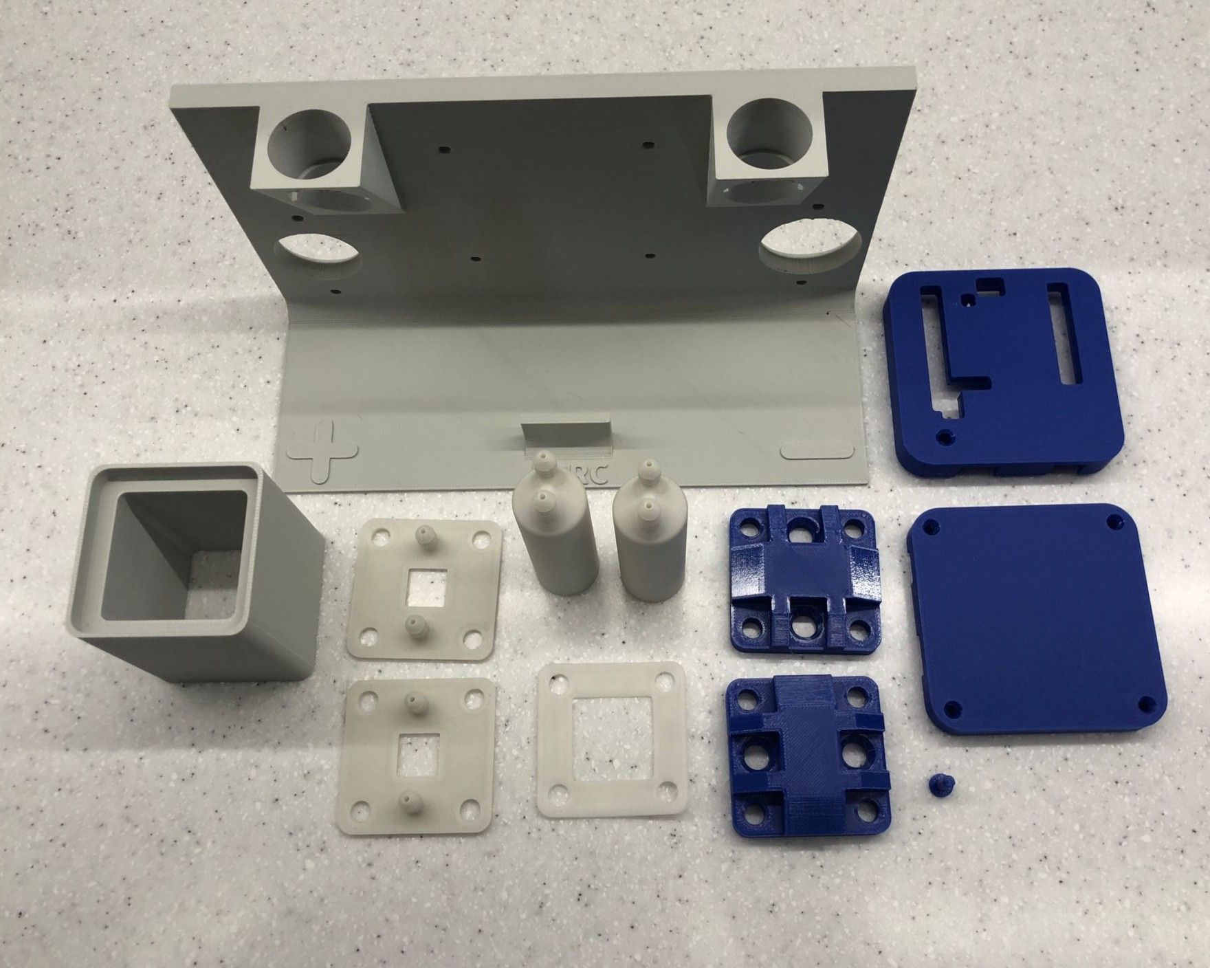
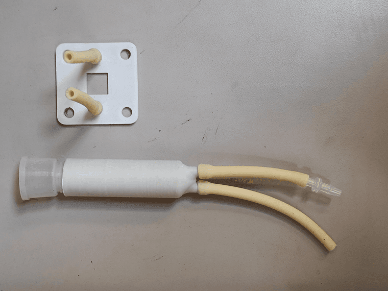
2x 6.5 cm (connect to reservoir inlet, barbed fitting adapter)This is what it looks like for one flow frame and one reservoir:
For electrical connections, these small bullet connectors are ideal, but you need to match them to your potentiostat cables - some folks are using different hardware here so I haven't spec'ed them yet. Alligator/crocodile clips are passable for initial tseting but really not ideal (can lead cause measurement error!). A non-ergonomic but quick fix option is to directly wire the bare MYSTAT wires to the current collectors with a screw.
I'll work tomorrow on updating the docs to reflect all this and spec'ing some hardware, will try to make another video of the cell assembly as well, with all the tubing present
-
Hi! I'm happy to have the opportunity to learn this based on your experience

I'm attaching a photo of my 3.2 x 6.4 mm tubing—hopefully it's the correct one.
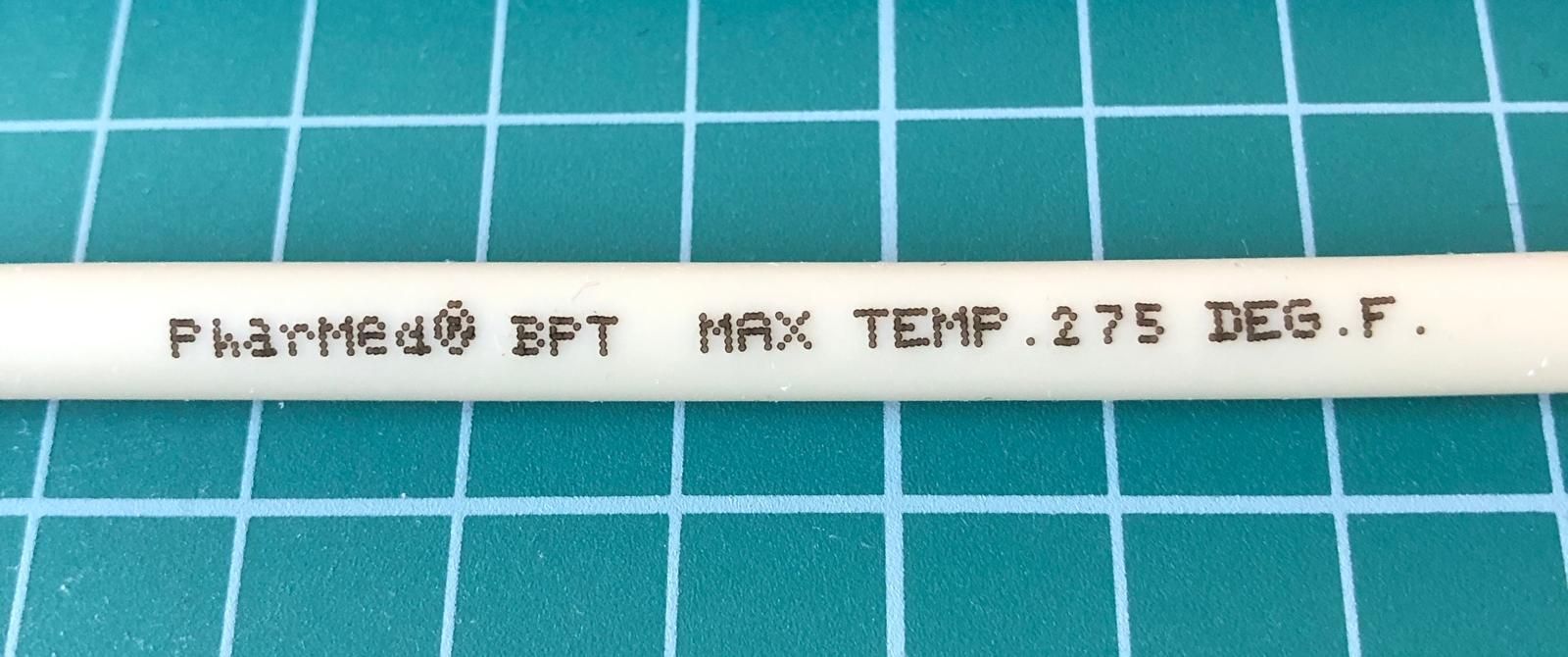
It seems that the default tubes in the Kamoer KPK200 pumps are already Pharmed BPT, so I assume there's no need to replace them - is that correct?
Oh, you mentioned a barbed fitting adapter now, but it wasn’t listed in the bill of materials - do I actually need it, or can I manage without it?
And yes, I’m using the MYSTAT potentiostat.
A guide showing how to connect all the cables between the pumps, Arduino, MYSTAT, and the power supply would be really helpful for me.
-
Hi! I'm happy to have the opportunity to learn this based on your experience
I'm attaching a photo of my 3.2 x 6.4 mm tubing—hopefully it's the correct one.
It seems that the default tubes in the Kamoer KPK200 pumps are already Pharmed BPT, so I assume there's no need to replace them - is that correct?
Oh, you mentioned a barbed fitting adapter now, but it wasn’t listed in the bill of materials - do I actually need it, or can I manage without it?
And yes, I’m using the MYSTAT potentiostat.
A guide showing how to connect all the cables between the pumps, Arduino, MYSTAT, and the power supply would be really helpful for me.
@gus said in Following your documentation – feedback & questions:
I'm attaching a photo of my 3.2 x 6.4 mm tubing—hopefully it's the correct one.
You will be able to make connections and leak test using water with this! Also, this tubing can stand up to Zn-I testing, but not within the pumps themselves - see below.
@gus said in Following your documentation – feedback & questions:
It seems that the default tubes in the Kamoer KPK200 pumps are already Pharmed BPT, so I assume there's no need to replace them - is that correct?
Regrettably, for the Zn-I testing, you need to replace the stock tubing in the KPK200 pumps with this tubing: https://fbrc.codeberg.page/rfb-dev-kit/tubing.html , it can also be ordered directly from Kamoer on Alibaba (may be hectic right now with tariffs in case you are based in the US). Warning, the process is annoying, but doable. I haven't documented it yet, only thrown the tubing in the BOM so that people can get it.
However we hope that an all-copper chemistry will play well with the stock BPT tubing, so hang tight on that. That chemistry operates using the exact same principle/hardware as we use for Zn-I and could be more forgiving in terms of chemical compatability.
@gus said in Following your documentation – feedback & questions:
Oh, you mentioned a barbed fitting adapter now, but it wasn’t listed in the bill of materials - do I actually need it, or can I manage without it?
Shoot, I will add this to the BOM - the ones we have leftover from our various pumps we've tested - I need to find a supplier link for just the fitting. For a leak test, you can get by without it, it just makes removing the cell from the jig much more ergonomic. The FDM-printed barbs can be difficult to install the tubing onto, the adapter allows you to break the connection from the cell and the reservoir without removing an FDM-printed barb connection. That way, rebuilding cells goes faster.
@gus said in Following your documentation – feedback & questions:
A guide showing how to connect all the cables between the pumps, Arduino, MYSTAT, and the power supply would be really helpful for me.
Got it, I'm on it!
-
While assembling the flow cell, I noticed that the manual doesn't mention anything about the Membrane Frame. I also have doubts whether the Membrane Frame model provided on the website isn't too thin (0.8 mm) to ensure a proper seal when using 4 membranes made from 230g/m² matte photo paper. Each membrane, according to my measurements, is 0.3 mm thick — which means the total thickness is 0.4 mm greater than the Membrane Frame's thickness. I also used 0.1 mm gaskets (as specified in the Bill of Materials), so such a large difference in thickness is unlikely to be compensated.
@kirk, do I need a thicker Membrane Frame or thicker inner gaskets? -
We have used the Membrane Frame on-and-off through some of our testing as we tested different separator materials and thicknesses. I just went back and checked some old notes, we did a lot of testing with three layers of photopaper in the end, so go ahead and just use three layers for now! I see one section of the docs said four layers and another said three, as well as the old photo.
-
We have used the Membrane Frame on-and-off through some of our testing as we tested different separator materials and thicknesses. I just went back and checked some old notes, we did a lot of testing with three layers of photopaper in the end, so go ahead and just use three layers for now! I see one section of the docs said four layers and another said three, as well as the old photo.
@kirk said in Following your documentation – feedback & questions:
We have used the Membrane Frame on-and-off through some of our testing as we tested different separator materials and thicknesses. I just went back and checked some old notes, we did a lot of testing with three layers of photopaper in the end, so go ahead and just use three layers for now! I see one section of the docs said four layers and another said three, as well as the old photo.
*use three-layers of photopaper and the membrane frame, I meant to say!
-
Thank you @kirk . Yes, I had already understood it from your previous message.
I’ve finished the assembly and performed a leak test using demineralised water. The first attempt failed due to leaks in both reservoirs (see photo). After that, I made a small design change and increased the 3D printer’s flow rate for the infill. The new reservoirs seem fine now.
Did you encounter this problem too? How did you solve it?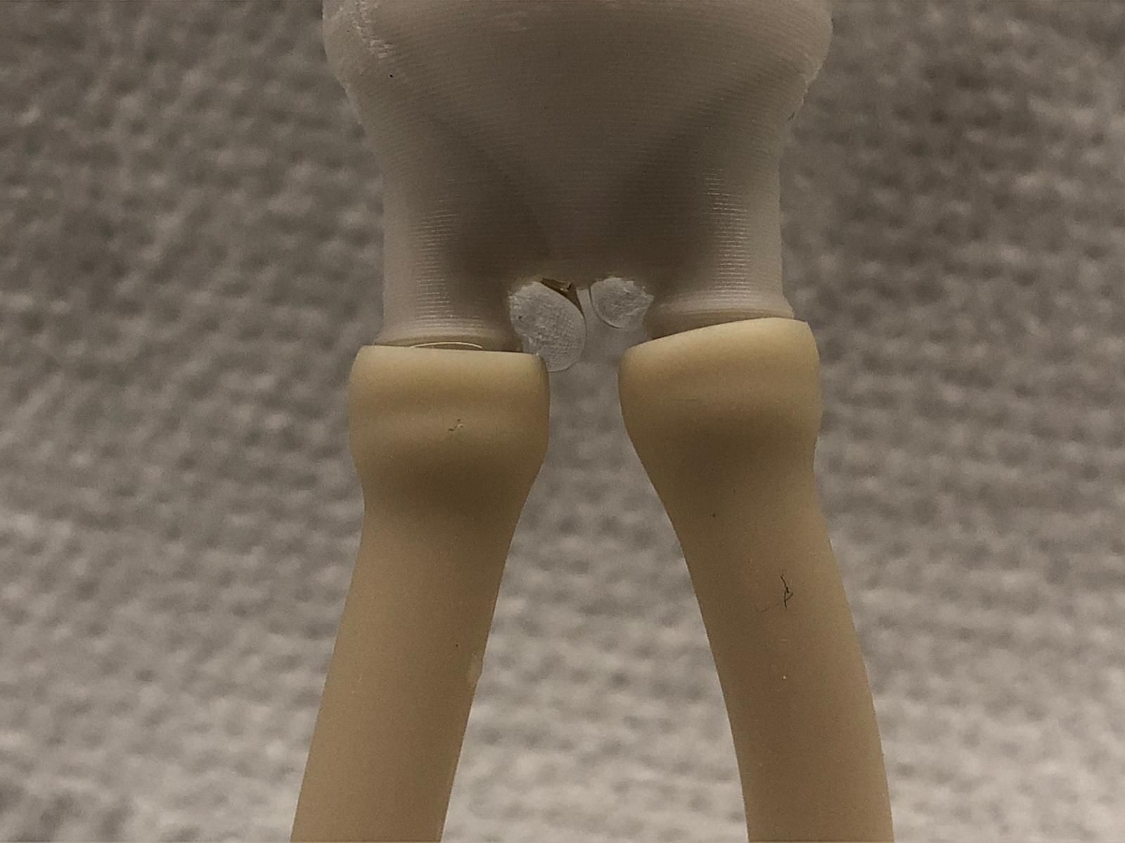
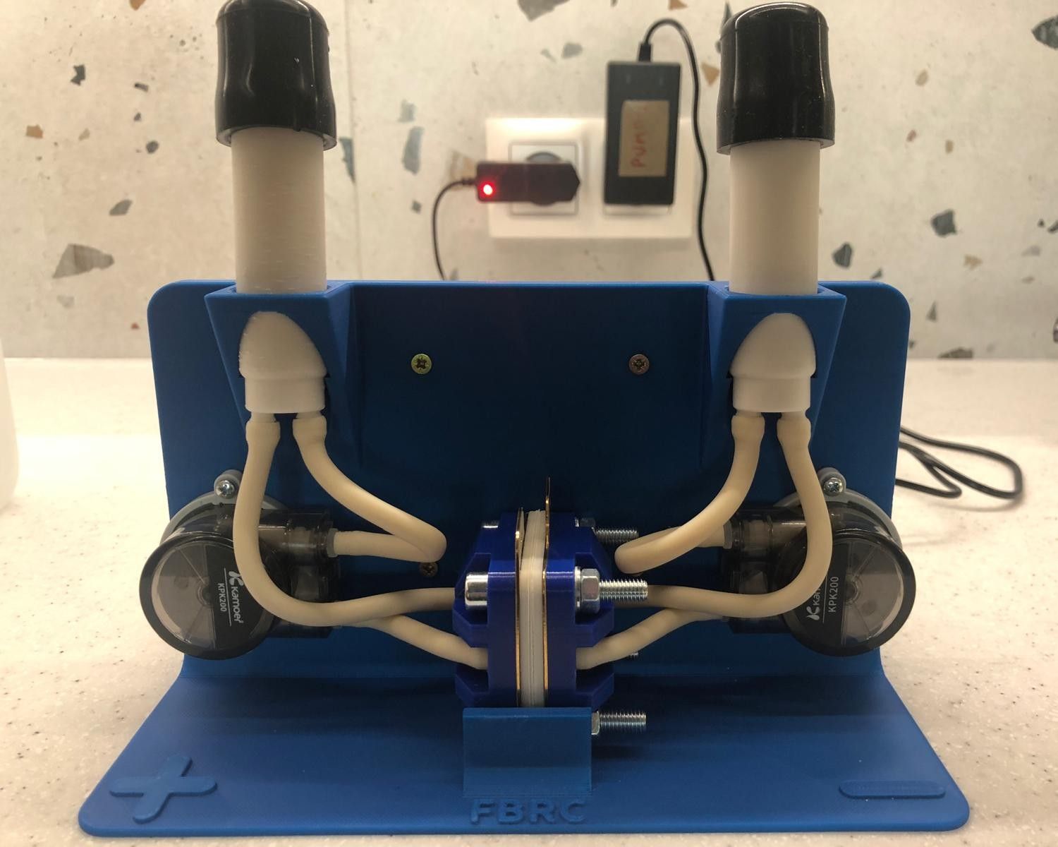
The cell itself doesn’t leak. I used a torque of 3 Nm for now, but it already looks slightly distorted. Have you considered using more bolts?
I also wanted to ask: is silicone resistant to this type of chemistry? Since it’s used for gaskets, maybe silicone tubing could be used as well?
Regarding the Arduino program: it seems there are four defined pins — In1 (pin 9), In2 (pin 8), In3 (pin 7), and In4 (pin 6) — but they don't appear to serve any purpose.
As for the main Python program — should it work with no issues once the Arduino and MYSTAT are connected to the computer?
-
@gus, awesome work! This is so exciting to see you've independently replicated the setup. Apologies on the delay for the pump wiring, I have recorded the raw video of me setting it all up as well as the pin numbers and I am in the process of editing it and updating the docs to match.
@gus said in Following your documentation – feedback & questions:
The new reservoirs seem fine now.
Did you encounter this problem too? How did you solve it?Our best strategy against leaking in PP prints has been 100% infill, 5 perimeters. I know some have success with slight overextrusion / flowrate multiplier of up to, say, 1.02 times. We have had reservoirs leak there before but tuning print settings usually leads to a tight reservoir. Could you share the file you modified? It looks like you added a big cylinder.
@gus said in Following your documentation – feedback & questions:
The cell itself doesn’t leak. I used a torque of 3 Nm for now, but it already looks slightly distorted. Have you considered using more bolts?
I think we need a stiffer endplate - similar hole pattern geometry, just thicker. This is an area to improve for sure, it's not ideal as-is. In the CAD files we have specified a 2D endplate (https://codeberg.org/FBRC/RFB-dev-kit/src/branch/main/CAD/exports/Metal Endplate.step), that could be laser cut or milled from aluminum. @danielfp@chemisting.com has received endplate versions of this in aluminum, the only catch is then you need insulating washers so as to not short them. Another rigid polymer could work too.
@gus said in Following your documentation – feedback & questions:
I also wanted to ask: is silicone resistant to this type of chemistry? Since it’s used for gaskets, maybe silicone tubing could be used as well?
We've tested and silicone tubing doesn't work for zinc-iodide, unfortunately. The gasket application of silicone is forgiving enough that it seems to work for this purpose, however, but we may be pushing our luck.
@gus said in Following your documentation – feedback & questions:
Regarding the Arduino program: it seems there are four defined pins — In1 (pin 9), In2 (pin 8), In3 (pin 7), and In4 (pin 6) — but they don't appear to serve any purpose.
These are legacy pins from when we used to use an H-bridge driver for different motors, before we got these stepper motors with built-in drivers.
This code is outdated, I have the new code but it's on my lab PC which is offline right now
 I am going to upload it soon.
@gus said in Following your documentation – feedback & questions:
As for the main Python program — should it work with no issues once the Arduino and MYSTAT are connected to the computer?
The program here * should * work on linux when run as root (in order to have proper USB access). You can control the pump speeds via the Arduino with the software, even without the MYSTAT connected (under the "charge/discharge" tab) (this will all hopefully be in a video soon!)
I'll have some more info soon (tomorrow hopefully?)
-
Thank you @kirk . Yes, I had already understood it from your previous message.
I’ve finished the assembly and performed a leak test using demineralised water. The first attempt failed due to leaks in both reservoirs (see photo). After that, I made a small design change and increased the 3D printer’s flow rate for the infill. The new reservoirs seem fine now.
Did you encounter this problem too? How did you solve it?The cell itself doesn’t leak. I used a torque of 3 Nm for now, but it already looks slightly distorted. Have you considered using more bolts?
I also wanted to ask: is silicone resistant to this type of chemistry? Since it’s used for gaskets, maybe silicone tubing could be used as well?
Regarding the Arduino program: it seems there are four defined pins — In1 (pin 9), In2 (pin 8), In3 (pin 7), and In4 (pin 6) — but they don't appear to serve any purpose.
As for the main Python program — should it work with no issues once the Arduino and MYSTAT are connected to the computer?
@gus said in Following your documentation – feedback & questions:
The cell itself doesn’t leak. I used a torque of 3 Nm for now, but it already looks slightly distorted. Have you considered using more bolts?
In our meeting today, @quinnale mentioned that in their lab they use 1.5-2 Nm max to tighten a similar size of flow cell. @danielfp@chemisting.com also builds his FBRC cells without a torque wrench, by tightening them only as much as he can holding the short end of the allen key.
-
@gus, awesome work! This is so exciting to see you've independently replicated the setup. Apologies on the delay for the pump wiring, I have recorded the raw video of me setting it all up as well as the pin numbers and I am in the process of editing it and updating the docs to match.
@gus said in Following your documentation – feedback & questions:
The new reservoirs seem fine now.
Did you encounter this problem too? How did you solve it?Our best strategy against leaking in PP prints has been 100% infill, 5 perimeters. I know some have success with slight overextrusion / flowrate multiplier of up to, say, 1.02 times. We have had reservoirs leak there before but tuning print settings usually leads to a tight reservoir. Could you share the file you modified? It looks like you added a big cylinder.
@gus said in Following your documentation – feedback & questions:
The cell itself doesn’t leak. I used a torque of 3 Nm for now, but it already looks slightly distorted. Have you considered using more bolts?
I think we need a stiffer endplate - similar hole pattern geometry, just thicker. This is an area to improve for sure, it's not ideal as-is. In the CAD files we have specified a 2D endplate (https://codeberg.org/FBRC/RFB-dev-kit/src/branch/main/CAD/exports/Metal Endplate.step), that could be laser cut or milled from aluminum. @danielfp@chemisting.com has received endplate versions of this in aluminum, the only catch is then you need insulating washers so as to not short them. Another rigid polymer could work too.
@gus said in Following your documentation – feedback & questions:
I also wanted to ask: is silicone resistant to this type of chemistry? Since it’s used for gaskets, maybe silicone tubing could be used as well?
We've tested and silicone tubing doesn't work for zinc-iodide, unfortunately. The gasket application of silicone is forgiving enough that it seems to work for this purpose, however, but we may be pushing our luck.
@gus said in Following your documentation – feedback & questions:
Regarding the Arduino program: it seems there are four defined pins — In1 (pin 9), In2 (pin 8), In3 (pin 7), and In4 (pin 6) — but they don't appear to serve any purpose.
These are legacy pins from when we used to use an H-bridge driver for different motors, before we got these stepper motors with built-in drivers.
This code is outdated, I have the new code but it's on my lab PC which is offline right now
I am going to upload it soon.@gus said in Following your documentation – feedback & questions:
As for the main Python program — should it work with no issues once the Arduino and MYSTAT are connected to the computer?
The program here * should * work on linux when run as root (in order to have proper USB access). You can control the pump speeds via the Arduino with the software, even without the MYSTAT connected (under the "charge/discharge" tab) (this will all hopefully be in a video soon!)
I'll have some more info soon (tomorrow hopefully?)
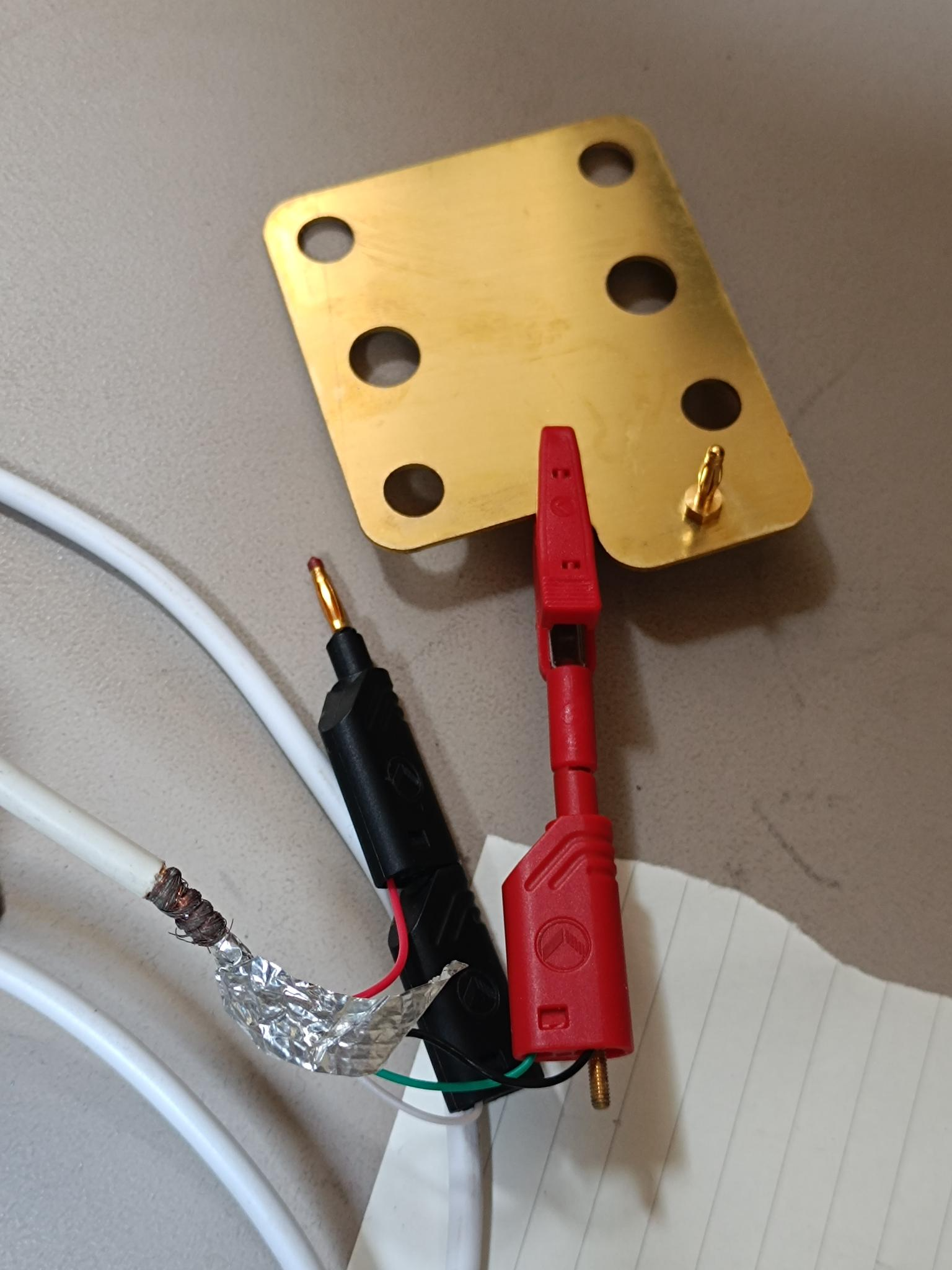
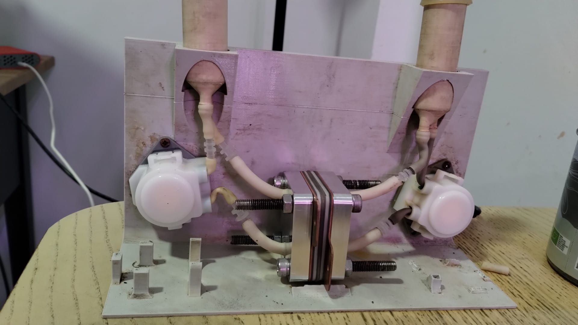
@kirk said in Following your documentation – feedback & questions:
In the CAD files we have specified a 2D endplate (https://codeberg.org/FBRC/RFB-dev-kit/src/branch/main/CAD/exports/Metal Endplate.step), that could be laser cut or milled from aluminum. @danielfp@chemisting.com has received endplate versions of this in aluminum, the only catch is then you need insulating washers so as to not short them. Another rigid polymer could work too.
I found a pic of this setup:
-
@kirk said in Following your documentation – feedback & questions:
Could you share the file you modified? It looks like you added a big cylinder.
I have send you an email,
@kirk said in Following your documentation – feedback & questions:
The program here * should * work on linux when run as root (in order to have proper USB access). You can control the pump speeds via the Arduino with the software, even without the MYSTAT connected (under the "charge/discharge" tab) (this will all hopefully be in a video soon!)
Thank you. I am planning to use a Raspberry Pi for long-term tests. Are you using a Raspberry Pi too, or a PC?
@kirk said in Following your documentation – feedback & questions:
In the CAD files we have specified a 2D endplate (https://codeberg.org/FBRC/RFB-dev-kit/src/branch/main/CAD/exports/Metal Endplate.step), that could be laser cut or milled from aluminum. @danielfp@chemisting.com has received endplate versions of this in aluminum, the only catch is then you need insulating washers so as to not short them. Another rigid polymer could work too.
Thank you. For now, if there are no leaks during the long-term tests, I will not change these endplates.
And also, I wanted to ask you about the current collector's material – is brass a better option than pure copper? What was the criterion for the material type and thickness selection?
-
@gus said in Following your documentation – feedback & questions:
I have send you an email,
Received, thank you!
@gus said in Following your documentation – feedback & questions:
Thank you. I am planning to use a Raspberry Pi for long-term tests. Are you using a Raspberry Pi too, or a PC?
I am using an old laptop that was in our lab, but a Raspberry Pi would work fine. I usually install ZeroTier or similar and then VNC in for remote access.
@gus said in Following your documentation – feedback & questions:
And also, I wanted to ask you about the current collector's material – is brass a better option than pure copper? What was the criterion for the material type and thickness selection?
Brass is somewhat more corrosion-resistant than copper, which is why we specified it. 1 mm is an arbitrary first guess for a reasonable thickness that's stiff and conductive enough, we haven't done any calculations for this however.
-
Also, apologies for the wait, but here are some more detailed instructions on how to build and wire everything (though you seem to have figured it out)
A video to accompany the written documentation: https://spectra.video/w/nJ8XNYu1MXNPSDLKV3KVTh
Improved documentation page on the electronics: https://fbrc.codeberg.page/rfb-dev-kit/electronics.html
-
It's been a while, but I’ve just configured a Raspberry Pi and got the mystat.py script working alongside Mystat and the Arduino. It looks like the chemistry is ready as well. Could I ask you for some instructions on how to proceed with the test using the mystat.py script? There are multiple options available, and I want to make sure everything is set up correctly
")
-
It's been a while, but I’ve just configured a Raspberry Pi and got the mystat.py script working alongside Mystat and the Arduino. It looks like the chemistry is ready as well. Could I ask you for some instructions on how to proceed with the test using the mystat.py script? There are multiple options available, and I want to make sure everything is set up correctly
@gus Nice work! Please let me know what electrolyte, concentration and volume you want to run and I can give you some guidance on exact settings.
-
@sepi, @danielfp248 thanks :), @danielfp248, I have an exact electrolyte from the documentation https://fbrc.codeberg.page/rfb-dev-kit/electrolyte.html .
-
@sepi, @danielfp248 thanks :), @danielfp248, I have an exact electrolyte from the documentation https://fbrc.codeberg.page/rfb-dev-kit/electrolyte.html .
@gus Great! As a first test please run the following:
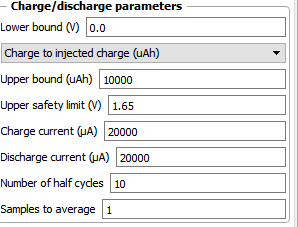
This should take around 1 one hour per charge/discharge cycle, experiment should take around 5 hours total. If the cycle ends because the potential reaches the upper safety limit too quickly, reduce the currents to 10000 and try again. At first the cells can require some time cycling at low SOC at lower current, to build all the Zn nucleation sites. Do not cycle to a potential higher than 1.7V because you will start having nasty side reactions at this point.
If this cycles successfully you can then increase the currents to 30000uA and repeat, see that it goes well.
After that you can then start going to high SOC values at 40000uA. I would recommend first cycling to 100mAh (set Upper bound to 100000uAh). Enclose the battery when cycling to higher SOC - you can put it inside a plastic tub - because leaks due to any problem will spray highly charged electrolyte, which, even if the volume is low, can be dangerous.
If you let me know how each test goes I can provide further feedback.
-
That sounds like even more exciting that I expected. @danielfp248 could you put this and a description of the wirering into the docs?
-
That sounds like even more exciting that I expected. @danielfp248 could you put this and a description of the wirering into the docs?
Hello! It looks like you're interested in this conversation, but you don't have an account yet.
Getting fed up of having to scroll through the same posts each visit? When you register for an account, you'll always come back to exactly where you were before, and choose to be notified of new replies (either via email, or push notification). You'll also be able to save bookmarks and upvote posts to show your appreciation to other community members.
With your input, this post could be even better 💗
Register Login