Designing the large-format cell
-
For the "large-format" cell, we'd like to target as large of a geometric area as possible, and ideally have the flow frame be useable both for single-cell and stack testing. This means it needs to possess adequate internal fluid manifolds and flow diffuser/spreading geometry. We must also consider shunt currents once we progress to stack testing, so we'd like to design the cell with that issue in mind upfront.
We plan to start with a flow-through design, as it is much, much simpler to design and manufacture than flow field-based approaches.
This thesis has some helpful figures - I haven't read it yet myself, but it looks quite useful. The author is now a professor at University of Padua.
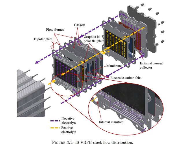
Basically we want to make our own version of this. Ideally we could prototype it with polypropylene FDM printing... but in any real application it would be injection molded.
A good image showing the path of a shunt current, which leads to a drop in energy efficiency as well as uneven current distribution (and possibly plating, for hybrid RFBs):
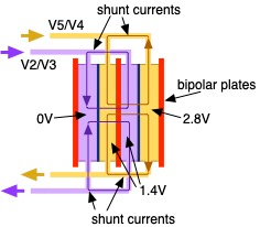
Image from University of Padua researchers: https://iopscience.iop.org/article/10.1149/MA2024-0217mtgabs
Right now, we need a flow frame that:
- Has the correct geometry for flow-through graphite felt electrodes (and possibly polymer felts/spacers, for hybrid chemistries)
- Doesn't leak
- Distributes flow evenly through the felts
- Offers adequate pressure drop and shunt currents when implemented in a stack
References
PhD thesis: https://www.research.unipd.it/handle/11577/3422708
Optimization paper: https://doi.org/10.1016/j.electacta.2021.139667
Flow field optimization paper (we don't have flow fields, but the simulation framework/procedure is interesting): https://linkinghub.elsevier.com/retrieve/pii/S0378775321009563
-
We would like to design our flow frame using an open-source toolchain like we have the kit. I can make a rough design of the flow frame in FreeCAD.
We will need to do some FEM and fluid mechanics simulations on this design, in addition to shunt current calcultations.
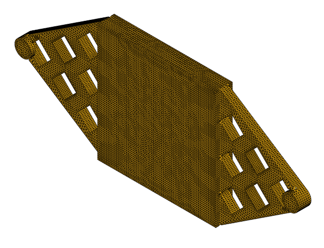
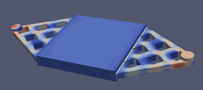
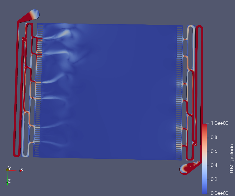
For fluid FEM and pressure drop/flow distribution, we could probably use OpenFOAM. There is a plug-in workbench to run this directly in FreeCAD, I have messed around with it and gotten it working on my laptop. I can run simulations in less than a minute for the small cell barbed flow frame:
FreeCAD + OpenFOAM (CfdOF)
This is something I did up quickly for the dev kit flow frame (2 sq cm).
Minimum working example for CFD that produced the above simulation results: https://codeberg.org/FBRC/RFB-dev-kit/media/commit/215285a9ef93c7eaaf68583418111a83b9d7b0e7/CAD/CFD.FCStd
Mesh:
Flow distribution:
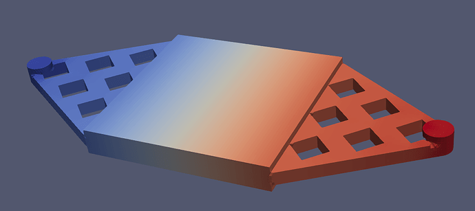
Pressure drop:
For shunt currents (and pressure drop too), we are probably best off manually calculating them first. They will depend on:
- Electrolyte conductivity
- Electrolyte viscosity
- Flow rate
- Manifold cross-section area
- Flow frame geometry
- and more...

-
 K kirk referenced this topic on
-
Probably too far involved but this sort of approach could be cool, if it was constrained to manufacturable shapes:
We introduce Fireshape, an open-source and automated shape optimization toolbox for the finite element software Firedrake. Fireshape is based on the moving mesh method and allows users with minimal shape optimization knowledge to tackle with ease challenging shape optimization problems constrained to partial differential equations (PDEs).
-
 K kirk@social.coop shared this topic on
-
I've just finished the CAD assembly of the first iteration of the large-format cell, which we will manufacture and test for leaks and other issues.
The repository is here.
Active area is currently 175 cm², and flow frames are hopefully printable on a 200 mm x 200 mm FDM printer. The flow frame is sized to fit on the printbed and still leave room for a healthy brim.
Manufacturing files in
CAD/exports.Filename Process/Material Quantity endplate-EndplateBolt Holes.step12 mm (1/2 in) plywood/MDF 2 outer-current-collector-Outer Current Collector.step1 mm brass 2 flow-frame-Flow Frame - Barbed, For Single Cell, Northeast.stlFDM / PP or ABS 1 flow-frame-back-Flow Frame (Back).stlFDM / PP or ABS 1 Gasket.svgTBD - thin <0.5 mm gasket material 3 Outer Gasket.svgTBD - thin <0.5 mm gasket material 1 Inner Current Collector.svg1 mm graphite foil 2 M10x50 bolts/nuts/washers 12 All flow connections are on one flow frame, which passes the other electrolyte through to the next half cell through internal manifolds.
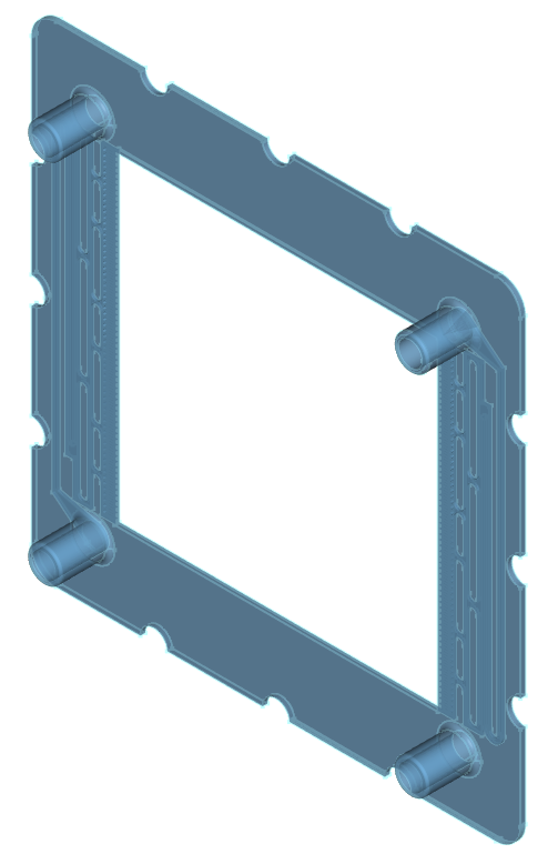
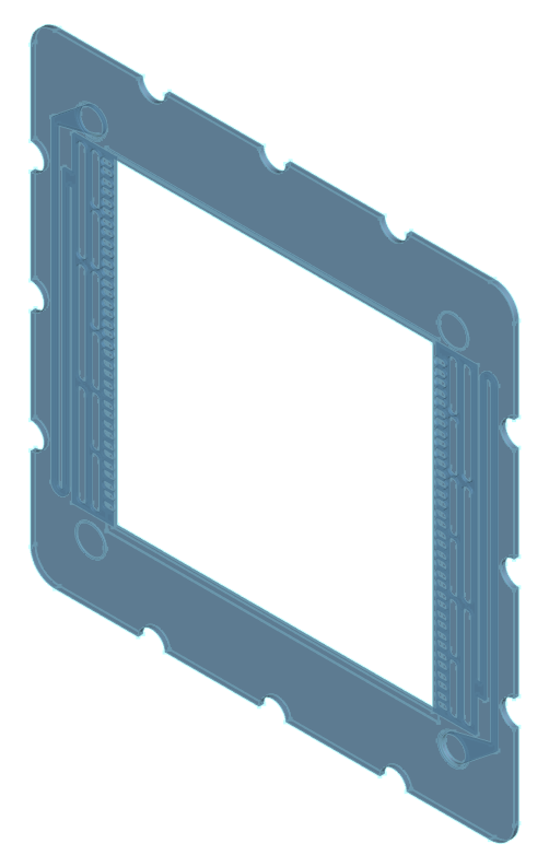
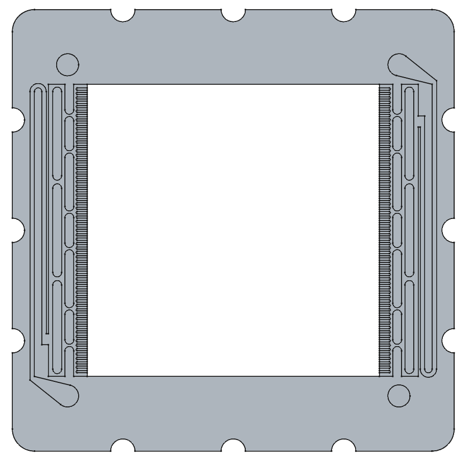
There are some shunt current flow paths and flow diffuser geometry in place, but these are not optimized and mostly representative. We will see if this type of geometry is even printable/sealable before spending much effort on CFD/FEM/shunt current modeling. This general approach is, however, roughly consistent with what I've seen in applied research and industry.

The "back" flow frame doesn't have barbs, and connects through the barbed flow frames internal manifolds to receive/output flow. It's flow fields are mirrored versions of the other flow frame, and the backside of this flow frame is completely blocked.
For endplates, the design is a simple flat sheet. We will see how 12mm plywood holds up with a 12-bolt pattern. Eight of these bolts straddle evenly the four barbed flow ports. There is a tab cutout for the current collector connection. Instead of making the current collector tab longer, I decided to cut out the endplate slightly like this, so that the current collector is cheaper to make on services like SendCutSend (which calculates largely on rectangular part area, and brass >> plywood for these thicknesses). Technically, only need the large 20 mm port holes on one side of this cell, since all the barbs are on the same side, but to keep unique part count/costs down when ordering and simplicity for now, I haven't created separate port-hole-less parts yet for the endplate and inner/outer current collectors.
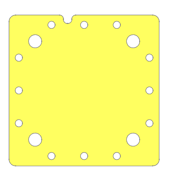
Gaskets and inner current collectors all largely follow the shape of the flow frames, with the
Outer Gasket.svghaving larger port holes to allow the barbs through.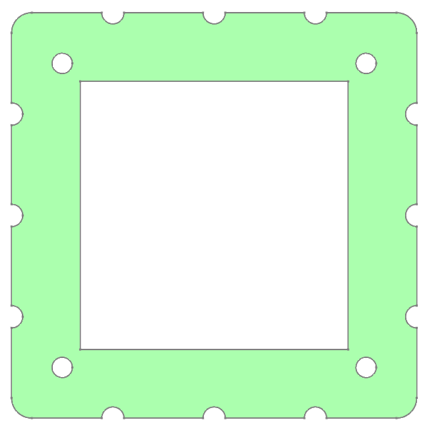
I've also modeled the pump we're using:
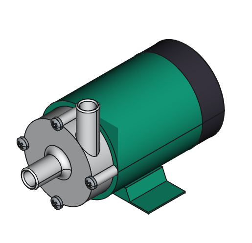
The code to control the pumps using an Arduino Uno and thyristors is here, and a corresponding GUI based on the MYSTAT software is here.
I haven't written any documentation yet because things are still changing quite a lot right now - I'll keep posting updates in this thread as we progress!
-
I've just finished the CAD assembly of the first iteration of the large-format cell, which we will manufacture and test for leaks and other issues.
The repository is here.
Active area is currently 175 cm², and flow frames are hopefully printable on a 200 mm x 200 mm FDM printer. The flow frame is sized to fit on the printbed and still leave room for a healthy brim.
Manufacturing files in
CAD/exports.Filename Process/Material Quantity endplate-EndplateBolt Holes.step12 mm (1/2 in) plywood/MDF 2 outer-current-collector-Outer Current Collector.step1 mm brass 2 flow-frame-Flow Frame - Barbed, For Single Cell, Northeast.stlFDM / PP or ABS 1 flow-frame-back-Flow Frame (Back).stlFDM / PP or ABS 1 Gasket.svgTBD - thin <0.5 mm gasket material 3 Outer Gasket.svgTBD - thin <0.5 mm gasket material 1 Inner Current Collector.svg1 mm graphite foil 2 M10x50 bolts/nuts/washers 12 All flow connections are on one flow frame, which passes the other electrolyte through to the next half cell through internal manifolds.
There are some shunt current flow paths and flow diffuser geometry in place, but these are not optimized and mostly representative. We will see if this type of geometry is even printable/sealable before spending much effort on CFD/FEM/shunt current modeling. This general approach is, however, roughly consistent with what I've seen in applied research and industry.
The "back" flow frame doesn't have barbs, and connects through the barbed flow frames internal manifolds to receive/output flow. It's flow fields are mirrored versions of the other flow frame, and the backside of this flow frame is completely blocked.
For endplates, the design is a simple flat sheet. We will see how 12mm plywood holds up with a 12-bolt pattern. Eight of these bolts straddle evenly the four barbed flow ports. There is a tab cutout for the current collector connection. Instead of making the current collector tab longer, I decided to cut out the endplate slightly like this, so that the current collector is cheaper to make on services like SendCutSend (which calculates largely on rectangular part area, and brass >> plywood for these thicknesses). Technically, only need the large 20 mm port holes on one side of this cell, since all the barbs are on the same side, but to keep unique part count/costs down when ordering and simplicity for now, I haven't created separate port-hole-less parts yet for the endplate and inner/outer current collectors.
Gaskets and inner current collectors all largely follow the shape of the flow frames, with the
Outer Gasket.svghaving larger port holes to allow the barbs through.I've also modeled the pump we're using:
The code to control the pumps using an Arduino Uno and thyristors is here, and a corresponding GUI based on the MYSTAT software is here.
I haven't written any documentation yet because things are still changing quite a lot right now - I'll keep posting updates in this thread as we progress!
This post is deleted! -
This post is deleted!
@wordmark@mas.to do you mean in general or in the context of this RFB cell? Ideally, we won't be generating any detectable H2 or O2, in practice, the flow paths in some cells are arranged so that the cell can be placed in a way where the fluid flows through the porous electrode upward, against gravity. If side reactions that generate H2 or O2 occur, and you make bubbles, those will ideally clear through the cell upward in the direction of flow.
-
Daniel has been prototyping this design, he made a post about it here: https://fbrc.nodebb.com/topic/9baae384-75b5-40bc-ae3c-de14abd8f8e4/working-on-a-large-scale-open-source-flow-battery-design-and-kit
-
I've just finished the CAD assembly of the first iteration of the large-format cell, which we will manufacture and test for leaks and other issues.
The repository is here.
Active area is currently 175 cm², and flow frames are hopefully printable on a 200 mm x 200 mm FDM printer. The flow frame is sized to fit on the printbed and still leave room for a healthy brim.
Manufacturing files in
CAD/exports.Filename Process/Material Quantity endplate-EndplateBolt Holes.step12 mm (1/2 in) plywood/MDF 2 outer-current-collector-Outer Current Collector.step1 mm brass 2 flow-frame-Flow Frame - Barbed, For Single Cell, Northeast.stlFDM / PP or ABS 1 flow-frame-back-Flow Frame (Back).stlFDM / PP or ABS 1 Gasket.svgTBD - thin <0.5 mm gasket material 3 Outer Gasket.svgTBD - thin <0.5 mm gasket material 1 Inner Current Collector.svg1 mm graphite foil 2 M10x50 bolts/nuts/washers 12 All flow connections are on one flow frame, which passes the other electrolyte through to the next half cell through internal manifolds.
There are some shunt current flow paths and flow diffuser geometry in place, but these are not optimized and mostly representative. We will see if this type of geometry is even printable/sealable before spending much effort on CFD/FEM/shunt current modeling. This general approach is, however, roughly consistent with what I've seen in applied research and industry.
The "back" flow frame doesn't have barbs, and connects through the barbed flow frames internal manifolds to receive/output flow. It's flow fields are mirrored versions of the other flow frame, and the backside of this flow frame is completely blocked.
For endplates, the design is a simple flat sheet. We will see how 12mm plywood holds up with a 12-bolt pattern. Eight of these bolts straddle evenly the four barbed flow ports. There is a tab cutout for the current collector connection. Instead of making the current collector tab longer, I decided to cut out the endplate slightly like this, so that the current collector is cheaper to make on services like SendCutSend (which calculates largely on rectangular part area, and brass >> plywood for these thicknesses). Technically, only need the large 20 mm port holes on one side of this cell, since all the barbs are on the same side, but to keep unique part count/costs down when ordering and simplicity for now, I haven't created separate port-hole-less parts yet for the endplate and inner/outer current collectors.
Gaskets and inner current collectors all largely follow the shape of the flow frames, with the
Outer Gasket.svghaving larger port holes to allow the barbs through.I've also modeled the pump we're using:
The code to control the pumps using an Arduino Uno and thyristors is here, and a corresponding GUI based on the MYSTAT software is here.
I haven't written any documentation yet because things are still changing quite a lot right now - I'll keep posting updates in this thread as we progress!
This post is deleted! -
For the "large-format" cell, we'd like to target as large of a geometric area as possible, and ideally have the flow frame be useable both for single-cell and stack testing. This means it needs to possess adequate internal fluid manifolds and flow diffuser/spreading geometry. We must also consider shunt currents once we progress to stack testing, so we'd like to design the cell with that issue in mind upfront.
We plan to start with a flow-through design, as it is much, much simpler to design and manufacture than flow field-based approaches.
This thesis has some helpful figures - I haven't read it yet myself, but it looks quite useful. The author is now a professor at University of Padua.
Basically we want to make our own version of this. Ideally we could prototype it with polypropylene FDM printing... but in any real application it would be injection molded.
A good image showing the path of a shunt current, which leads to a drop in energy efficiency as well as uneven current distribution (and possibly plating, for hybrid RFBs):
Image from University of Padua researchers: https://iopscience.iop.org/article/10.1149/MA2024-0217mtgabs
Right now, we need a flow frame that:
- Has the correct geometry for flow-through graphite felt electrodes (and possibly polymer felts/spacers, for hybrid chemistries)
- Doesn't leak
- Distributes flow evenly through the felts
- Offers adequate pressure drop and shunt currents when implemented in a stack
References
PhD thesis: https://www.research.unipd.it/handle/11577/3422708
Optimization paper: https://doi.org/10.1016/j.electacta.2021.139667
Flow field optimization paper (we don't have flow fields, but the simulation framework/procedure is interesting): https://linkinghub.elsevier.com/retrieve/pii/S0378775321009563
This post is deleted! -
Any particular reason why you don't consider milling or laser cutting? FDM printing large surfaces that need to stay flat seems to be a challenge on general. Have you envisioned printing the structure (manifold?) on a prefabricated sheed of plastic?
-
I saw the blog post which also mentioned the problems of 3d printing the panels of that size without warping. I did a quick google on injection molding and that could also get $$$ and a bit beyond some DIYers with the need for pressure.
But what about casting? Are there resin based or other low temp materials that could be cast? Because making the mold would be easy. A dummy part could be printed from any material and it could be made in, say forths that could be glued together. And for the mold there is a quick setting plaster like material we use in construction for repairs (one brand is "Quickfix) that dries to a porcelain like material, very hard, and very fast. It's sold with set times in minutes. Make your dummy part and put it on some wax paper or plastic wrap on a flat surface with a frame around the part. fill with plaster and when cured, spray with a sealer that wont react to the resin to seal the micro pores. Then with it flipped over and the dummy back in, and the frame around it, pour the other half. You have a simple and cheap to make mold for casting.
-
From the way I looked at the plate, it has open channels that become enclosed when placed against the next plate.
I've never done any 3d printing, but from what I read, they don't do overhangs well because the hot plastic would not have any support under it and adding supports in the channels would restrict flow.
-
This post is deleted!
@wordmark@mas.to said in Designing the large-format cell:
Previous thought: so u say this cell makes O2 and H2 going out from separate outlets?
No, that is not at all the intended operation, but it is a possible unintended side reaction if something goes wrong or is poorly designed/outside the operating mode.
@wordmark@mas.to said in Designing the large-format cell:
What volts amps will your stack require? Production costs per stack?
@wordmark@mas.to said in Designing the large-format cell:
what are the properties for such a battery? (How does it compare to a 48V 14kWh #LiFePo4? (Which can burn down houses if cells are not high quality)
We are very far from having a datasheet on such an RFB, as we are still very much in the R&D phase, but there are some datasheets out there from commercial companies which could give you an idea, but generally RFBs don't make sense below 10 kWh in size because of their size and requirement of centrifugal pumps.
We have a FAQ that might answer some of your questions here.
-
Any particular reason why you don't consider milling or laser cutting? FDM printing large surfaces that need to stay flat seems to be a challenge on general. Have you envisioned printing the structure (manifold?) on a prefabricated sheed of plastic?
@sepi said in Designing the large-format cell:
Any particular reason why you don't consider milling or laser cutting? FDM printing large surfaces that need to stay flat seems to be a challenge on general. Have you envisioned printing the structure (manifold?) on a prefabricated sheed of plastic?
I have considered this, and I'm not against it, I am just pursuing FDM first until I can prove that we need to try something else. With our current approach it's desirable for sealing purposes to have a flat, sealed top surface on the flow frame, ie overhanging geometry, so laser/milling are out, unless you try to bond a layer on top, and it starts to get complicated. Milling plastic, especially fine details, is also hard to do well for amateur machinists - it tends to just melt unless you have your speeds and feeds totally dialed + flood coolant. We hope to have an FDM printable design to allow as many others to get in on this, since FDM printers are much more abundant and easy to use than capable plastic CNC mill setups.
Printing on plastic sounds kind of hard, especially for PP filaments, and it doesn't get rid of the overhanging geometry question.
@sepi said in Designing the large-format cell:
Also did you ever consider TPU for the parts in contact with the electrodes? It's pretty resistant to chemicals and ribbery and could thus male seals.
We haven't tried TPU yet, if I recall @danielfp248 saw somewhere that it wouldn't be compatible with the zinc-iodide chemistry that has been our main workhorse - specifically the charged triiodide species, which is really a pain in terms of chemical resistance. We'd need to confirm that it's resistant to triiodide. You're right that it's flexibility could help make it a good seal though.
@sepi said in Designing the large-format cell:
I guess that both injection molding and casting don't allow for fancy internal geomtries needed for the manifolds.
Both injection molding and casting can do internal geometries, but as @Vorg pointed out it's cost prohibitive on small-scales.
@Vorg said in Designing the large-format cell:
I've never done any 3d printing, but from what I read, they don't do overhangs well because the hot plastic would not have any support under it and adding supports in the channels would restrict flow.
FDM printing can "bridge" to some extent, which we are exploiting to print our prototype flow frames here. @danielfp248 made a great post showing some of his efforts to print it here, I highly recommend you check that post out - we're definitely making progress with this approach! Eventually, if we got a really great flow frame design that was locked-in, it may make sense to make a lot of them with injection molding.
-
@wordmark@mas.to said in Designing the large-format cell:
Previous thought: so u say this cell makes O2 and H2 going out from separate outlets?
No, that is not at all the intended operation, but it is a possible unintended side reaction if something goes wrong or is poorly designed/outside the operating mode.
@wordmark@mas.to said in Designing the large-format cell:
What volts amps will your stack require? Production costs per stack?
@wordmark@mas.to said in Designing the large-format cell:
what are the properties for such a battery? (How does it compare to a 48V 14kWh #LiFePo4? (Which can burn down houses if cells are not high quality)
We are very far from having a datasheet on such an RFB, as we are still very much in the R&D phase, but there are some datasheets out there from commercial companies which could give you an idea, but generally RFBs don't make sense below 10 kWh in size because of their size and requirement of centrifugal pumps.
We have a FAQ that might answer some of your questions here.
This post is deleted! -
@wordmark@mas.to said in Designing the large-format cell:
Previous thought: so u say this cell makes O2 and H2 going out from separate outlets?
No, that is not at all the intended operation, but it is a possible unintended side reaction if something goes wrong or is poorly designed/outside the operating mode.
@wordmark@mas.to said in Designing the large-format cell:
What volts amps will your stack require? Production costs per stack?
@wordmark@mas.to said in Designing the large-format cell:
what are the properties for such a battery? (How does it compare to a 48V 14kWh #LiFePo4? (Which can burn down houses if cells are not high quality)
We are very far from having a datasheet on such an RFB, as we are still very much in the R&D phase, but there are some datasheets out there from commercial companies which could give you an idea, but generally RFBs don't make sense below 10 kWh in size because of their size and requirement of centrifugal pumps.
We have a FAQ that might answer some of your questions here.
This post is deleted!
Hello! It looks like you're interested in this conversation, but you don't have an account yet.
Getting fed up of having to scroll through the same posts each visit? When you register for an account, you'll always come back to exactly where you were before, and choose to be notified of new replies (either via email, or push notification). You'll also be able to save bookmarks and upvote posts to show your appreciation to other community members.
With your input, this post could be even better 💗
Register Login