Connecting potentiostat
-
Could you please document how the potentiostat is connected to the cell? Is it connected only on the two current collectors? Does that not mean that you could substitute it using a constant voltage source and just log current?
Sorry, I'm a total newcomer in battery testing, so this might be obvious to others.
-
Hi sepi, you could! I've done this with other flow cell systems. E.g., I've used one of these cheap DC power supplies and monitored the current using an INA219.
Potentiostats are generally better-designed and have more features: good time resolution, finer potential/current control, have a reference lead, often have potential limits, and provide more-complex waveforms (like scanning potentials).
Depending on the source, you might have to swap the leads to charge/discharge (i.e., if there is no negative bias).
Be wary of setting the potential too high on these DC power sources or you can destroy some of the electrode materials or generate a bunch of hydrogen / oxygen.
Again, doable, just some limitations! Hopefully I'm not forgetting any crucial ones here.
-
Oh right, to the first part of your question: yes, in this case the reference lead is connected to the counter electrode, such that the potential you apply and measure is across the entire cell. There is no third connection point. LMK if unclear and I can provide a picture or schematic later.
And pretty much. There are some fun additional tests you could do with a potentiostat that would be quite annoying (or impossible) to do with a simple power source. E.g., collect current at variable potential for a rapid "polarization curve". Or cyclic voltammetry to estimate the capacitance of the system.
Just depends on what you want to do and how "manual" you want to make certain measurements.
Also, you might need to find a different current measurement device that is sensitive to the right range (1-100s of mA it seems: https://fbrc.nodebb.com/topic/18/zinc-iodide/3). I forget the range of the one I shared, it might work?
-
I wouldn't mind a little diagram but don't go grazy (unless you would want o integrate it into the docs).
About the necessity of the potentiostat: I mainly ask since it's unfortinately not as easy to get and also quite expensive (>200€). I think I might just try building the rest of the cell first. That way, if I get demotivated midway, I won't have a "useless" potentiostat sitting around

-
I think a potentiostat is a must if you want to do proper quantitative experiments. However, not all experiments require it, you can definitely use a power supply with the ability to set constant current to charge the cell and then discharge it across some load to make it work. Using the time it takes to charge and discharge using a setup like this you can get charge and discharge capacity values, but Coulomb efficiency, Energy efficiency, etc will be outside your reach.
Potentiostats can also make experiments safer as you can establish limits for upper voltages or currents, make sure you do not overload the cells. It is important to not do this as this can cause clogging, gas generation, etc.
A potentiostat is the heart of modern battery research, I would give it a high priority if possible.
-
@quinnale Ahh, that makes sense to me. So I'd really use the potentiostat as a fancy DC power supply plus current logger in this case? I didn't miss a third electrode on the cell that could be connected as a reference potential?
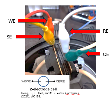
@sepi Here's that image I promised. In the paper from Irving et al. describing the MyStat, there is the 2-electrode diagram (on the bottom left of the image below) instructing one to connect the WE/SE together on one electrode, and the CE/RE on the other electrode.
Some terminology here
WE - working electrode
SE - sensing electrode (generally meant to measure potential at the WE)
CE - counter electrode
RE - reference electrode (here meant to measure potential at the CE, but in other setups can be placed elsewhere)You cannot separate WE/SE and CE/RE in a typical DC power supply.
I think it'd be fun to try power supply (and of course consider your resources), but I'll second danielfp248. Will also facilitate comparison to the data collected by others on here. A potentiostat could also open you up to 3-electrode beaker experiments, although that's another fun topic on its own (not covered in this forum).
-
Thanks a lot for the digging! You're probably right about getting potentiostat. I got the quote from PCBWay down to around 314$ for one fully assembled PCB and 4 extra ones. This is acceptable for me even if still quite expensive. I guess I could drive down the cost by ordering and soldering on the expensive parts by myself.
@sepi Unless you are very experienced soldering small components I would suggest not doing this. Some of the expensive components are tiny and easy to damage, either by overheating or by soldering multiple legs together and causing shorts. I tried soldering my own mystat 3 times (without success) before I got my first working one from pcbway. I am however, not good at all at soldering.
Hello! It looks like you're interested in this conversation, but you don't have an account yet.
Getting fed up of having to scroll through the same posts each visit? When you register for an account, you'll always come back to exactly where you were before, and choose to be notified of new replies (either via email, or push notification). You'll also be able to save bookmarks and upvote posts to show your appreciation to other community members.
With your input, this post could be even better 💗
Register Login