My build (very slowly progressing)
-
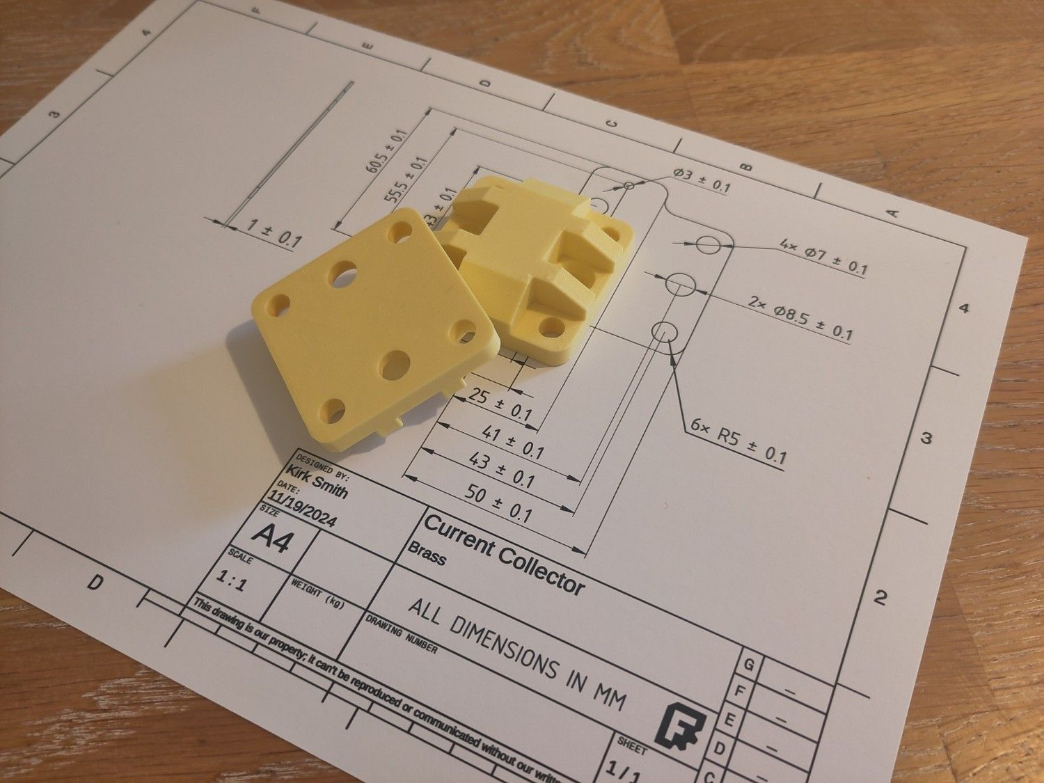
I finally managed to mill the current collectors. I started off with 0.9mm brass but had an accident with the second collector.
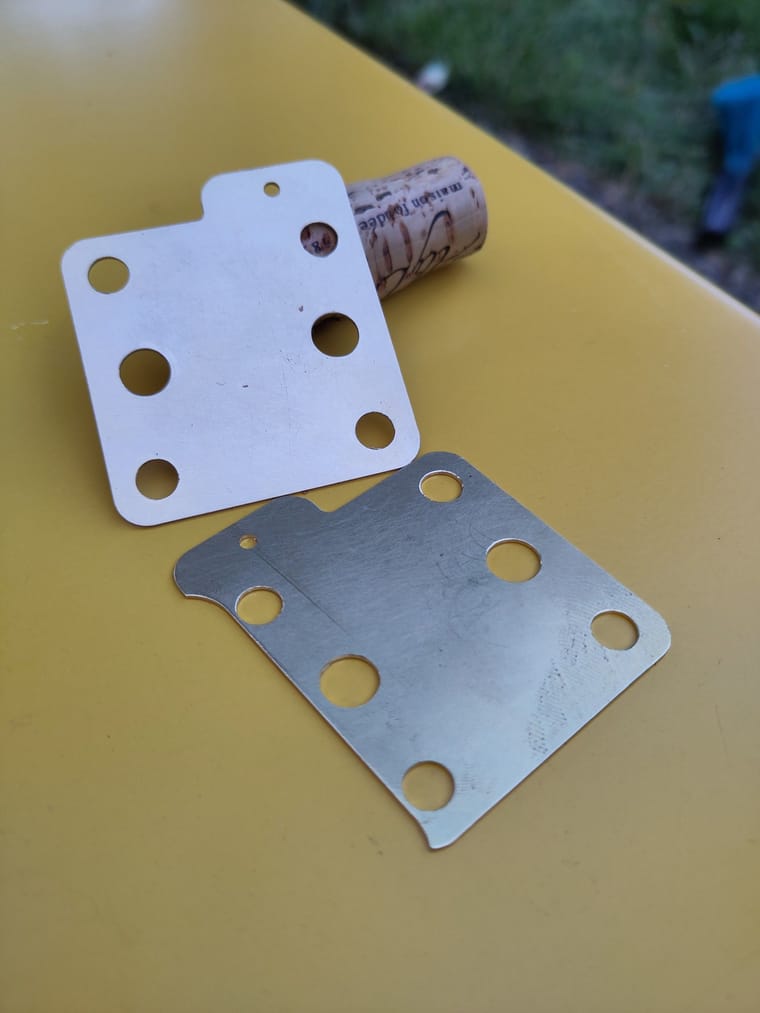 I'm pretty sure it would work, but to be sure I went to the crafts shop next door and got some 0.8mm copper and re-milmed the collectors.
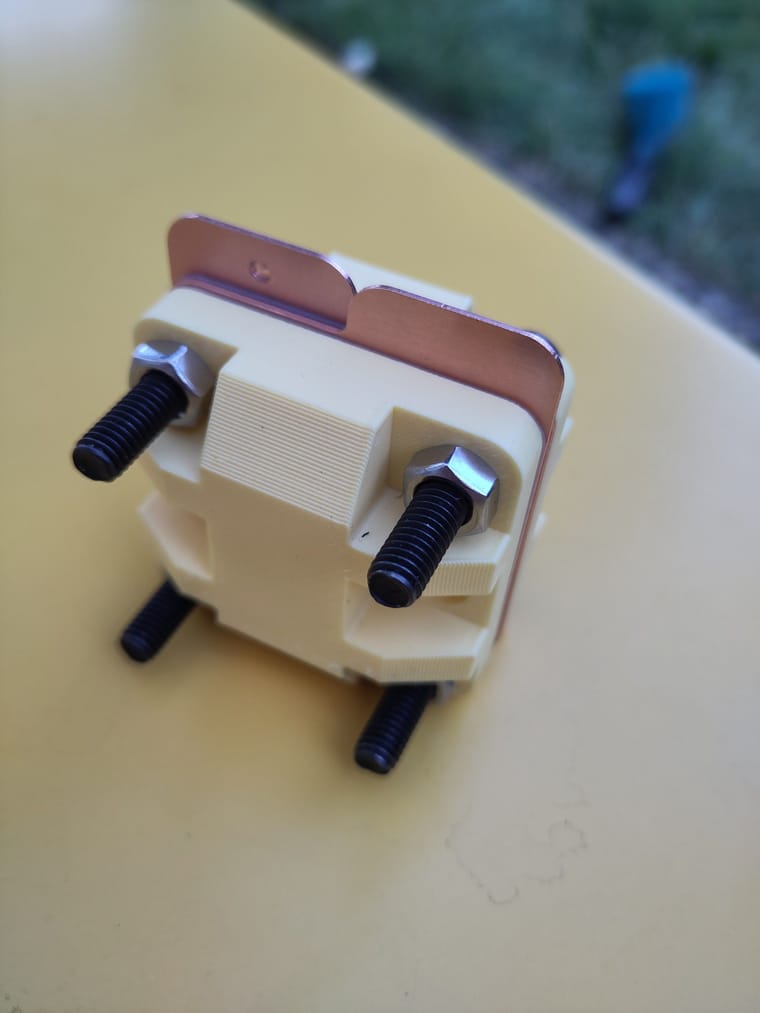 .
.The cell starts to come together!
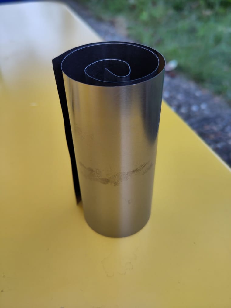
I also received the titanium foil which needs to be milled into the right shape to work as a bipolar plate. As a backup I also have generic grafoil being delivered.The only things I'm missing now is the pumps, proper PTFE lined tubing and PP-Filament.
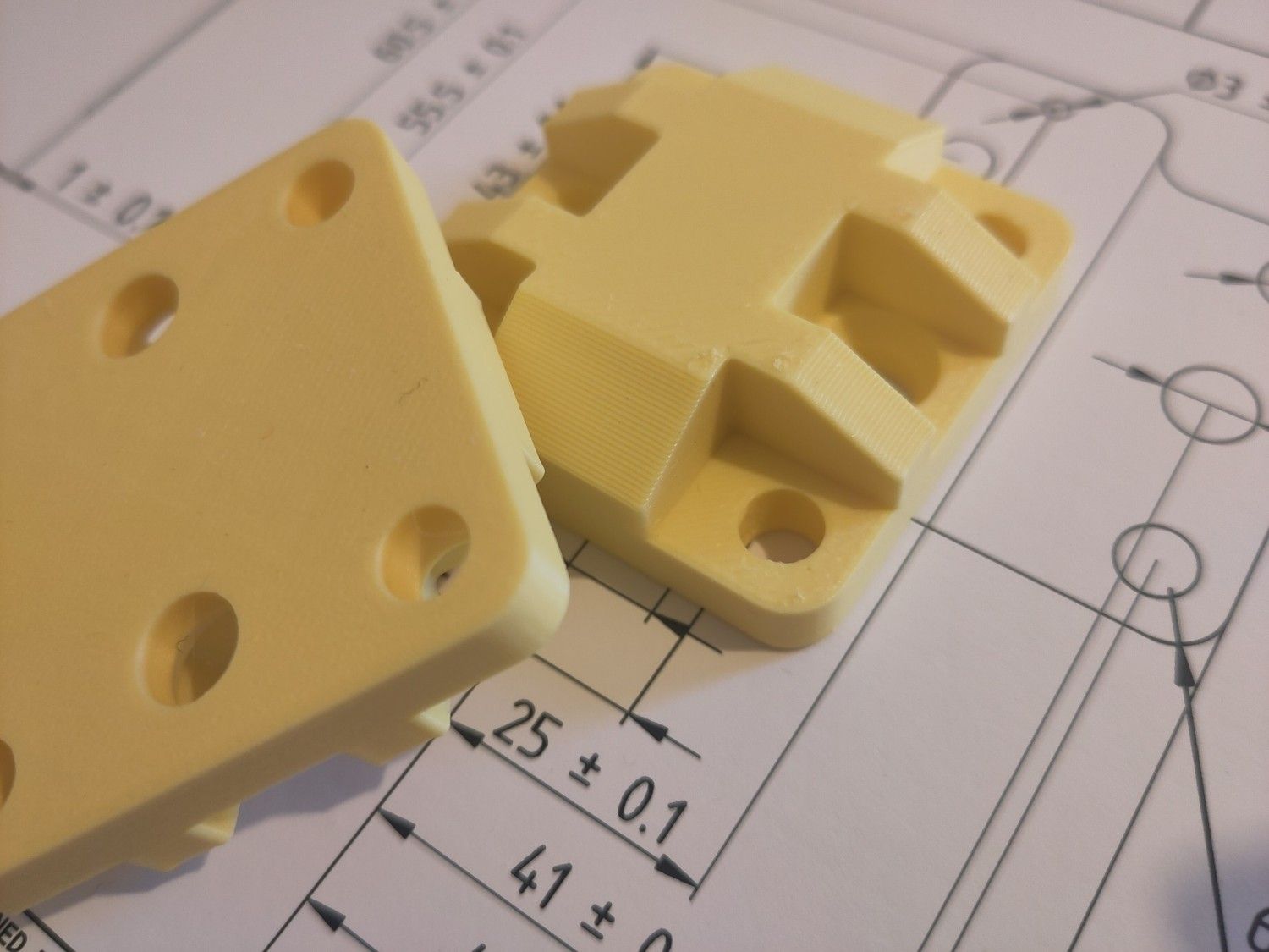
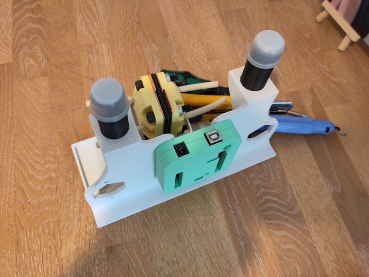
In the meantime I'll print my modified jig which tries to reduce print time and adds some printability features like hexagonal holes for the pumps and drop shaped holes for screws. It also features a little basin that can catch a bit of liquid that might spill.
-
I finally managed to mill the current collectors. I started off with 0.9mm brass but had an accident with the second collector.
I'm pretty sure it would work, but to be sure I went to the crafts shop next door and got some 0.8mm copper and re-milmed the collectors. .The cell starts to come together!
I also received the titanium foil which needs to be milled into the right shape to work as a bipolar plate. As a backup I also have generic grafoil being delivered.The only things I'm missing now is the pumps, proper PTFE lined tubing and PP-Filament.
In the meantime I'll print my modified jig which tries to reduce print time and adds some printability features like hexagonal holes for the pumps and drop shaped holes for screws. It also features a little basin that can catch a bit of liquid that might spill.
@sepi Great work! Please feel free to post your modified STL files for the jig here. We always welcome community improvements!
-
Also note, those screws look like black steel. They will get heavily corroded just from tiny amounts of iodide contact when you assemble/disassemble the battery. Ti screws are preferable if you want your screws to last, otherwise I would recommend changing your screws once they start rusting.
-
So the journey continues. I managed to cut the Ti electrodes to size. I used a regular household scisors to cut the outline and a cutter to do the holes. After using a deburring tool, the holes were a bit less dangerous but still highly deformed.
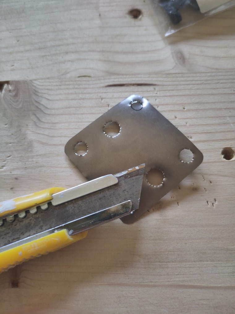
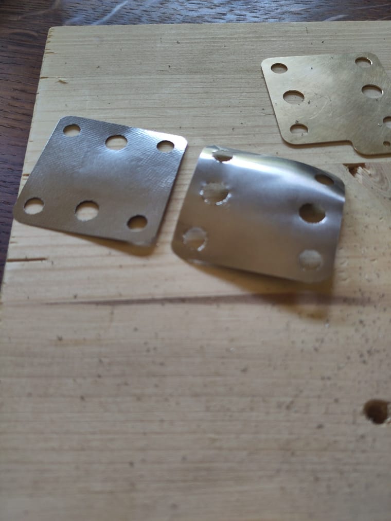
I then used a metal vise to press the edges of the plates protected by two sheets of paper on each side. This created the criss cross structure. It makes the electrode nicely plane but might cause problems with contact.
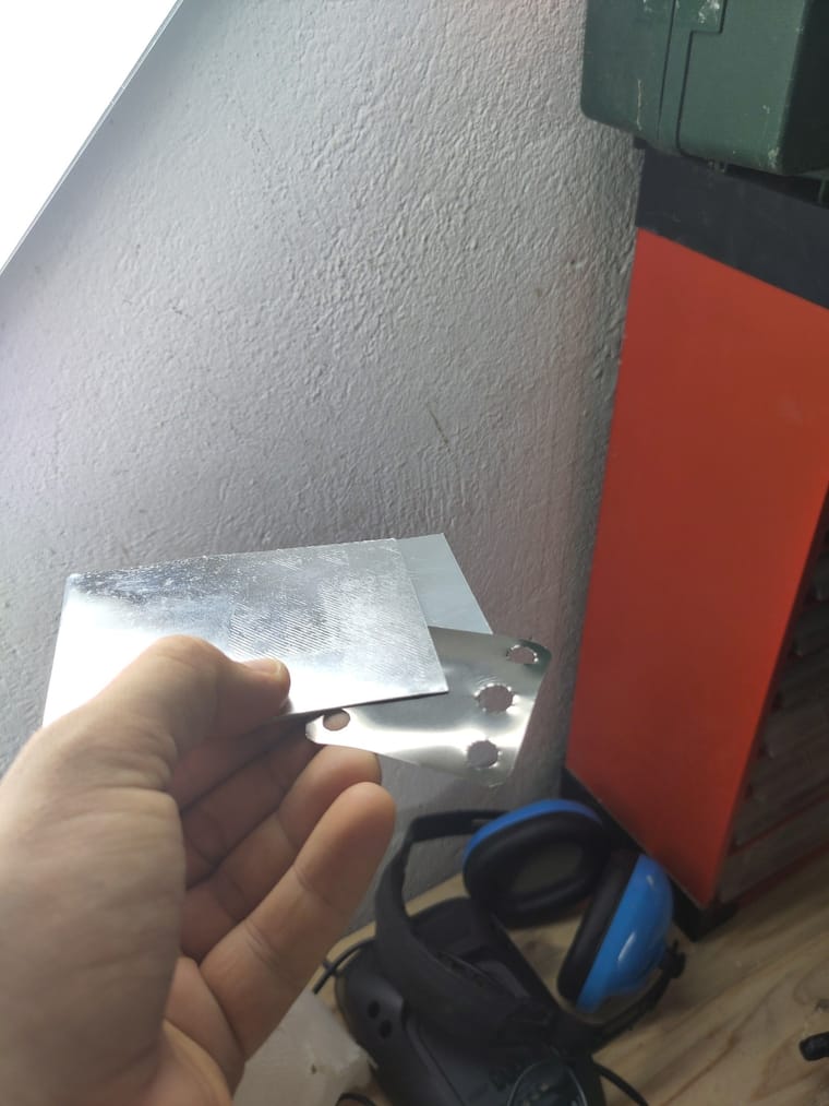
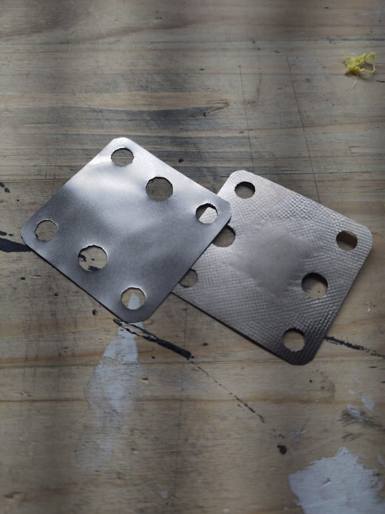
I tried sparing the inside, where the graphite felt contacts the electrode. For the second part, I used two pieces of sheet aluminium to protect the material from the vise structure. It worked but didn't make the part plane, so I re used the paper method for that part too. We'll see later if that's an issue I'll soon get some grafoil and still have some spare Ti foil left over.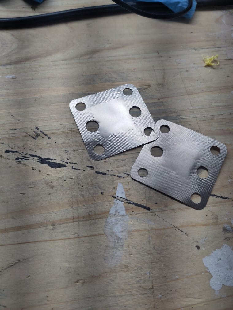
-
So the journey continues. I managed to cut the Ti electrodes to size. I used a regular household scisors to cut the outline and a cutter to do the holes. After using a deburring tool, the holes were a bit less dangerous but still highly deformed.
I then used a metal vise to press the edges of the plates protected by two sheets of paper on each side. This created the criss cross structure. It makes the electrode nicely plane but might cause problems with contact.
I tried sparing the inside, where the graphite felt contacts the electrode. For the second part, I used two pieces of sheet aluminium to protect the material from the vise structure. It worked but didn't make the part plane, so I re used the paper method for that part too. We'll see later if that's an issue I'll soon get some grafoil and still have some spare Ti foil left over.@sepi Nice to see you were able to get the Ti electrodes cut! Ti is a really hard metal, so edges generated by any cutting process that uses pressure are going to be really sharp (be really careful with them!). I don't think you're going to have a lot of contact issues because under cell compression contact will likely be more than good enough between this and the current collector. If need be you could add a little bit of electrically conductive silver paste between both to maximize conductivity if the surface is not smooth. However this isn't likely to be necessary for your first tests, only to maximize efficiency if you wish to do so.
-
I got around printing the PP parts and it's not going great I'm afraid. The parts either don't stick (on PEI plate) or stick too much on PP tape. Even adding a layer of mineral oil doesn't help too much. The tape itself is also not very even due to bubbles. The top is also not super smooth. Who knows, maybe the gasket can seal anyways.
On the plus side, the electrolyte containers seem to be good.
Now I need to be patient about the Pumps from Kamoer which have't shipped yet and the Potentiostat wich also isn't completed yet.
I'm more and more considering printing my own centrifugal pump with magnetic coupling. This could also be interesting for the larger models as good pumps seem to be pretty expensive.
@sepi Great job starting to print PP! Your pieces look good! You don't have to remove the packing tape, if the tape stays on the piece when you put it inside the cell, it's fine, the PP tape is basically melted onto the piece and it's the same material, so it's chemically compatible with the electrolytes too. If you want a clean result without tape I would recommend either using the special PP surface from Prusa or buying a surface from PPPPrint (https://www.ppprint.de/en/produkt/surface/). Both of these solutions worked great for me.
Also, I would say the gasket can probably seal those surfaces well enough, provided the piece is water tight.
-
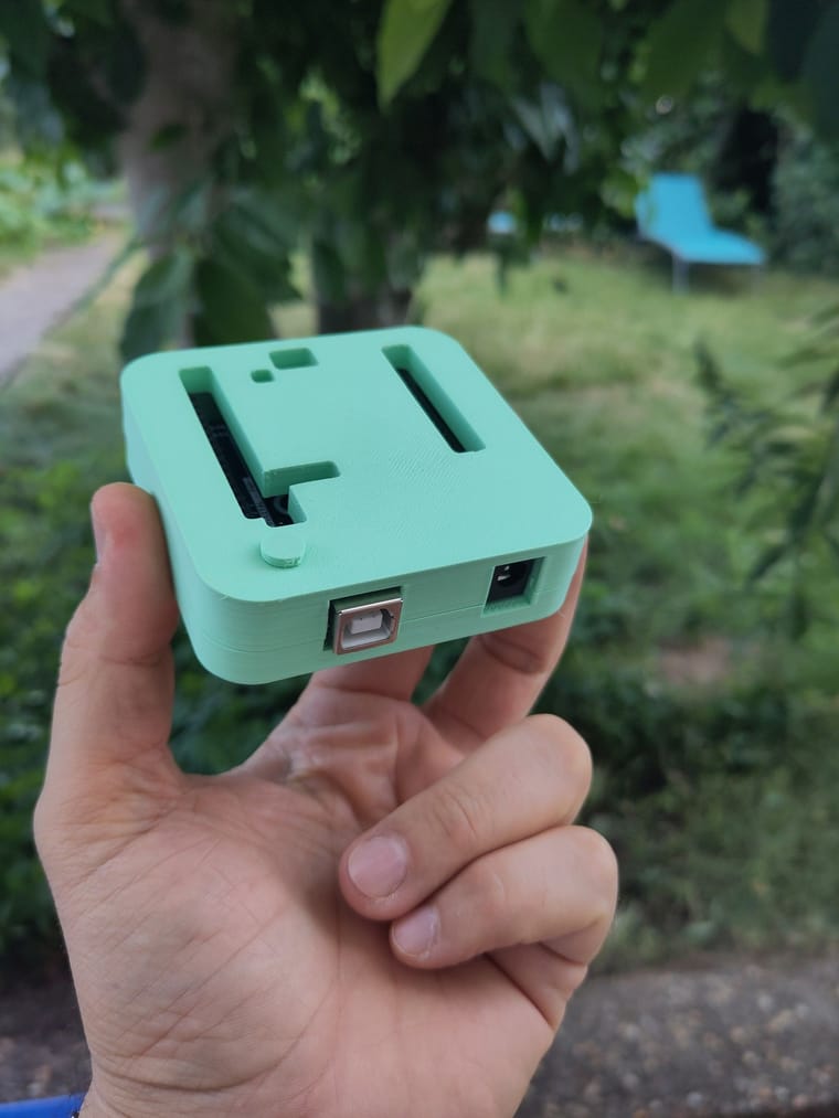
So I mades some progress. I finished the raspi case without much fuss (although I must say it could be designed to use a bit less plastic). The button does not work, it's just a tiny bit short. Maybe because my UNO is super old and used a different button.
I also received some tubing by Camoer but unfortunately I ordered the variant without PTFE inner lining. Apparently I can still use it for cycling until capacity of 50%. Let's see if I can get the correct one quickly enough.
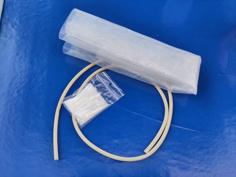
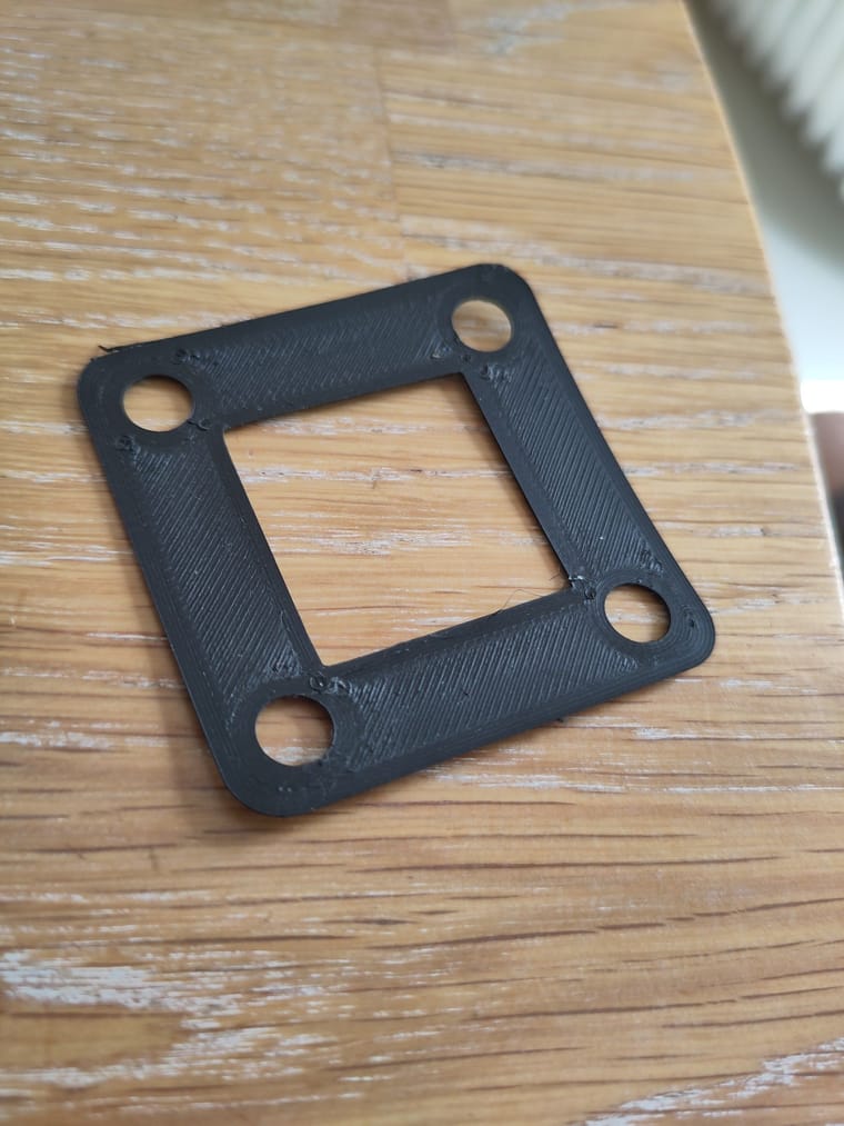
I also received my first baggy of ... KI from amazon. The rest of the chemicals are coming from some dutch web shop. And finally, the gasket 0.5 silikone film arrived. I tried manually cutting gaskets, with more or less succes.
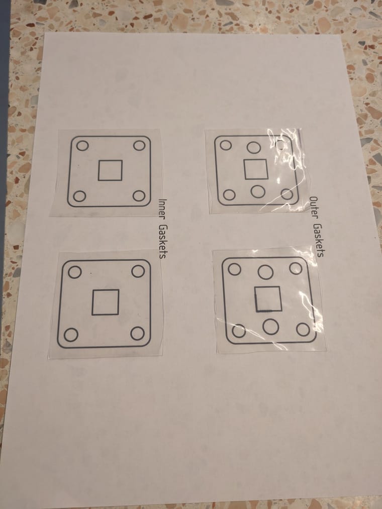
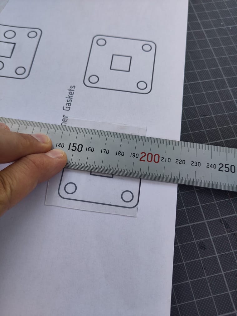
Only testing can tell of it will work :).
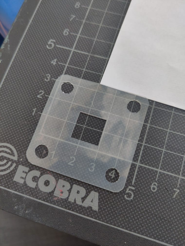
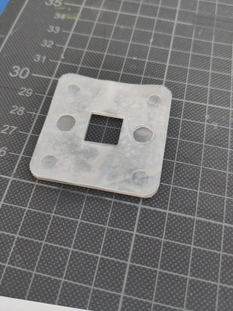
They align ok, but I'm not really sure what will be important in the end.
@sepi said in My build (very slowly progressing):
The button does not work, it's just a tiny bit short. Maybe because my UNO is super old and used a different button.
FYI, that button is upside down which is why it doesn't work! You assemble it so that the large end is fixed inside the case (a bit of a balancing act during the assembly). The original designer has some photos of it assembled here: https://www.thingiverse.com/thing:628929
-
@sepi said in My build (very slowly progressing):
The button does not work, it's just a tiny bit short. Maybe because my UNO is super old and used a different button.
FYI, that button is upside down which is why it doesn't work! You assemble it so that the large end is fixed inside the case (a bit of a balancing act during the assembly). The original designer has some photos of it assembled here: https://www.thingiverse.com/thing:628929
@kirk Thanks for clarifying kirk, I have the same issue, lol.
-
I got around printing the PP parts and it's not going great I'm afraid. The parts either don't stick (on PEI plate) or stick too much on PP tape. Even adding a layer of mineral oil doesn't help too much. The tape itself is also not very even due to bubbles. The top is also not super smooth. Who knows, maybe the gasket can seal anyways.
On the plus side, the electrolyte containers seem to be good.
Now I need to be patient about the Pumps from Kamoer which have't shipped yet and the Potentiostat wich also isn't completed yet.
I'm more and more considering printing my own centrifugal pump with magnetic coupling. This could also be interesting for the larger models as good pumps seem to be pretty expensive.
@danielfp248 said in My build (very slowly progressing):
@kirk Thanks for clarifying kirk, I have the same issue, lol.
I have added a note to the docs on this now!
Also @sepi I somehow missed reading the main chunk of your thread that you posted several days ago - great work!!
@sepi said in My build (very slowly progressing):
Now I need to be patient about the Pumps from Kamoer which have't shipped yet
@quinnale has also tried some 3D-printed peristaltic pumps in his build thread: https://fbrc.nodebb.com/topic/23/towards-a-working-system
@sepi said in My build (very slowly progressing):
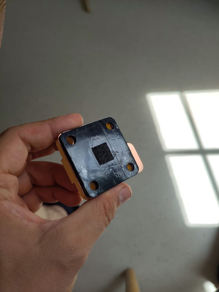
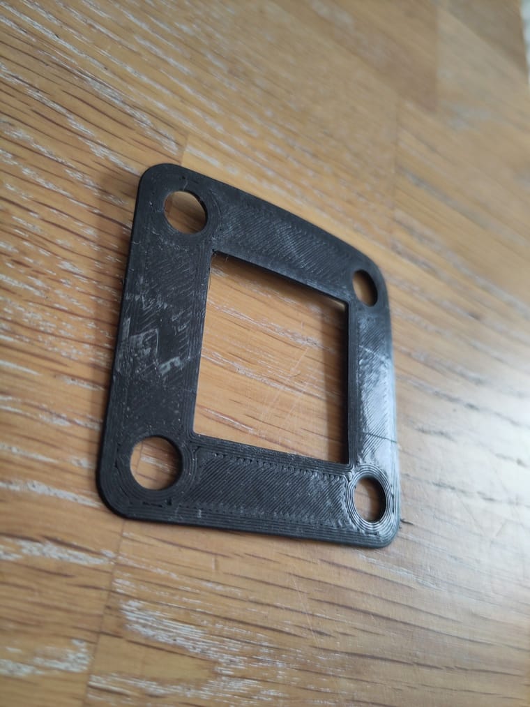
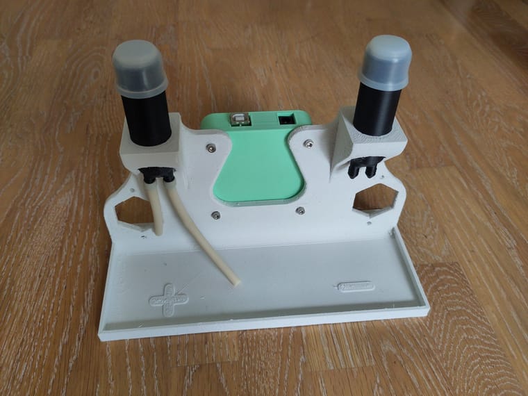
So I finally printed my modified jig in 6h on my kobra max with 1mm nozzle. This made it quick but fugly. You judge for yourself and maybe tell me why my modifications don't make sense.
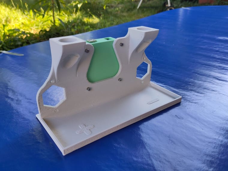
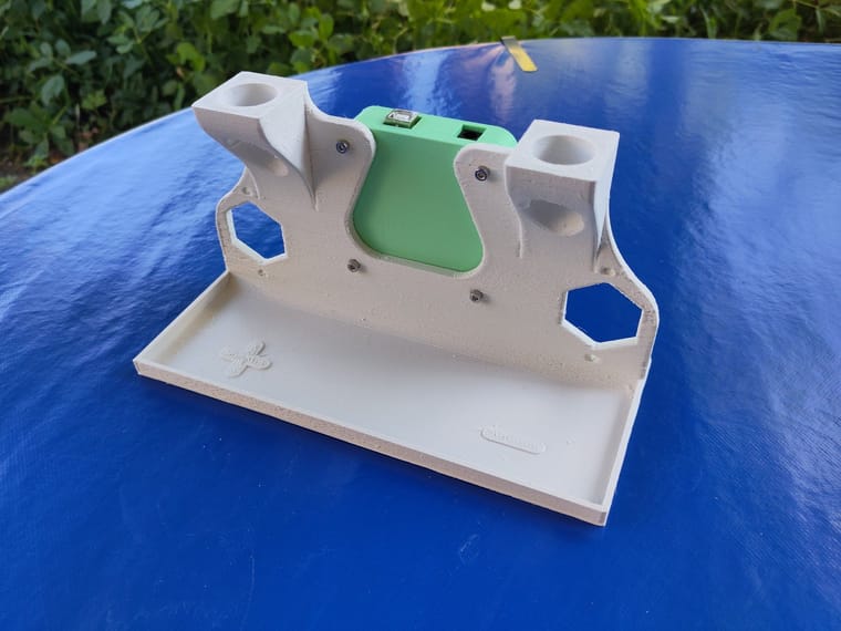
Can you show the back of your jig? If the rear support doesn't stick out long enough, the entire jig can tip over once the pumps are installed due to a shift in the center of gravity.
Also, it looks cool and wavy! And using a lot less material. Did you modify it in FreeCAD?
-
I got around printing the PP parts and it's not going great I'm afraid. The parts either don't stick (on PEI plate) or stick too much on PP tape. Even adding a layer of mineral oil doesn't help too much. The tape itself is also not very even due to bubbles. The top is also not super smooth. Who knows, maybe the gasket can seal anyways.
On the plus side, the electrolyte containers seem to be good.
Now I need to be patient about the Pumps from Kamoer which have't shipped yet and the Potentiostat wich also isn't completed yet.
I'm more and more considering printing my own centrifugal pump with magnetic coupling. This could also be interesting for the larger models as good pumps seem to be pretty expensive.
@sepi said in My build (very slowly progressing):
I'm more and more considering printing my own centrifugal pump with magnetic coupling. This could also be interesting for the larger models as good pumps seem to be pretty expensive.
If you do, please share the results! This may be very demanding of PP FDM printing (leaktightness, tolerances, etc.). For reference, these are the pumps we are planning on using for the large-format cell (they are likely too large, but the smallest PP, mag drive centrifugal pumps we could find): https://fbrc.nodebb.com/post/30. They were less than 50 EUR each at a quantity of 2 pumps, IIRC.
-
@sepi said in My build (very slowly progressing):
The button does not work, it's just a tiny bit short. Maybe because my UNO is super old and used a different button.
FYI, that button is upside down which is why it doesn't work! You assemble it so that the large end is fixed inside the case (a bit of a balancing act during the assembly). The original designer has some photos of it assembled here: https://www.thingiverse.com/thing:628929
-
@danielfp248 said in My build (very slowly progressing):
@kirk Thanks for clarifying kirk, I have the same issue, lol.
I have added a note to the docs on this now!
Also @sepi I somehow missed reading the main chunk of your thread that you posted several days ago - great work!!
@sepi said in My build (very slowly progressing):
Now I need to be patient about the Pumps from Kamoer which have't shipped yet
@quinnale has also tried some 3D-printed peristaltic pumps in his build thread: https://fbrc.nodebb.com/topic/23/towards-a-working-system
@sepi said in My build (very slowly progressing):
So I finally printed my modified jig in 6h on my kobra max with 1mm nozzle. This made it quick but fugly. You judge for yourself and maybe tell me why my modifications don't make sense.
Can you show the back of your jig? If the rear support doesn't stick out long enough, the entire jig can tip over once the pumps are installed due to a shift in the center of gravity.
Also, it looks cool and wavy! And using a lot less material. Did you modify it in FreeCAD?
-
@kirk about the jig, yeah I modified the FreeCAD version. It's probably prone to tipping. I'll see that once I get the pumps and hobo modify it and then modify my model and share it.
-
@sepi Great job, your assembly is really looking quite good. Can't wait to see how it will perform.
-
@czahl said in My build (very slowly progressing):
@sepi Your PP parts are looking good. Which filament did you used?
https://www.3djake.com/fiberlogy/r-pp-anthracite?sai=12757
It's pretty soft but that might just be PP. I never used PP before. I just selected the cheapest one on 3dJake.

Hello! It looks like you're interested in this conversation, but you don't have an account yet.
Getting fed up of having to scroll through the same posts each visit? When you register for an account, you'll always come back to exactly where you were before, and choose to be notified of new replies (either via email, or push notification). You'll also be able to save bookmarks and upvote posts to show your appreciation to other community members.
With your input, this post could be even better 💗
Register Login