Designing the large-format cell
-
@danielfp248 congrats! Is this plywood and is there any reason you could not manufacture this using regular woodworking tools, like a table saw and drill press? (Which I fortunately have at home
")
-
@danielfp248 congrats! Is this plywood and is there any reason you could not manufacture this using regular woodworking tools, like a table saw and drill press? (Which I fortunately have at home
@sepi It is not plywood it is birchwood (people who did the laser cutting didn't have plywood). You can manufacture this with normal wood working tools, I don't have any so it was just easier to order it. Important thing is that hole locations are correct and the wood be very flat. You definitely need a planer to achieve that.
-
If it's solid wood, there is a high chance that it will warp with changes in temperature and/or humidity. I guess it is some kind of plywood made from birch wood. Plywood is much less prone to warping due to the aforementionned external factors. In the end things might be different since the plates will be under pressure. I'm wondering if a structure a bit similar to what you did for the PLA endplates in the small battery might work. That's off course only if you run into trouble with your current, simple design.
-
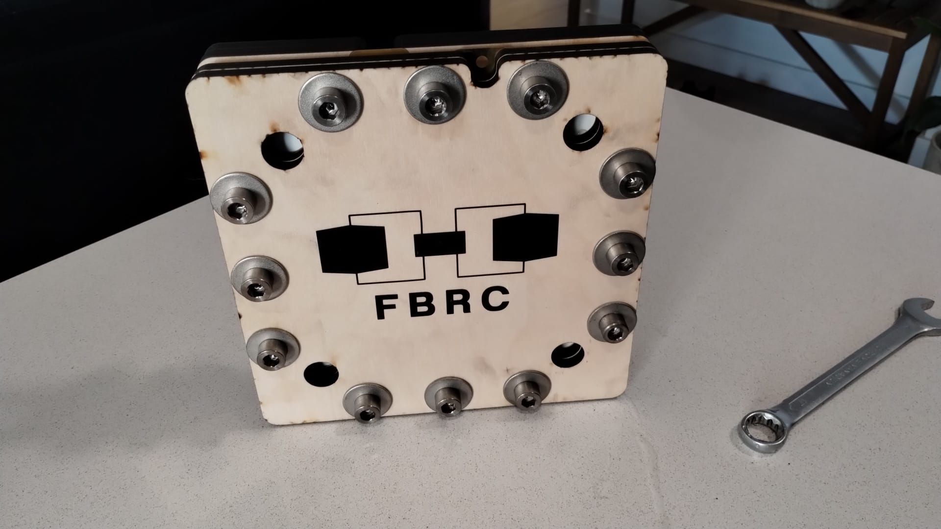
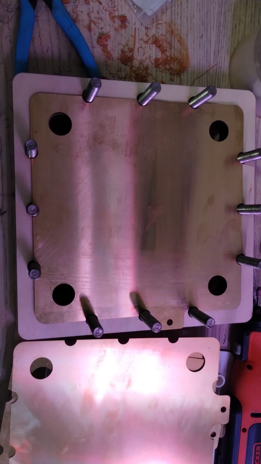
I just put together the first large scale cell and did a test with tap water recirculation to test if the geometry would work with no leaks. I didn't use any grafoil but just the bare brass current collectors, since I'm not doing any electrochemical testing right now.
There was a significant leak from one of the input ports as the pressure required to flow through the flow frame geometry was too high, but there were no leaks through the gaskets. We are going to be modifying the flow frame geometry to be the simplest possible, similar to the small scale kit. This way we can make sure we have a design that can flow at the lowest possible pressure and then we can scale complexity as required later on to improve shunt currents. We might also add barbs to the input ports to prevent this sort of leaking. We'll keep you posted on our progress!
Also, the wood did not warp on compression!
-
I'm 99% sure this is not possible, but maybe tossing it out there would give someone an idea for another direction to look. This problem of a shunt current makes my envision some sort of FET like object with a passage between source and drain to allow fluid to flow through it while a "gate voltage" pinches off current flow through it.
I know, crazy, but maybe now that it's out there, the thought will stop bouncing around in my head
-
I just put together the first large scale cell and did a test with tap water recirculation to test if the geometry would work with no leaks. I didn't use any grafoil but just the bare brass current collectors, since I'm not doing any electrochemical testing right now.
There was a significant leak from one of the input ports as the pressure required to flow through the flow frame geometry was too high, but there were no leaks through the gaskets. We are going to be modifying the flow frame geometry to be the simplest possible, similar to the small scale kit. This way we can make sure we have a design that can flow at the lowest possible pressure and then we can scale complexity as required later on to improve shunt currents. We might also add barbs to the input ports to prevent this sort of leaking. We'll keep you posted on our progress!
Also, the wood did not warp on compression!
@danielfp248 congrats, that sounds like a small win already! I'm looking forward to reading about your progress!
-
I'm 99% sure this is not possible, but maybe tossing it out there would give someone an idea for another direction to look. This problem of a shunt current makes my envision some sort of FET like object with a passage between source and drain to allow fluid to flow through it while a "gate voltage" pinches off current flow through it.
I know, crazy, but maybe now that it's out there, the thought will stop bouncing around in my head
@Vorg said in Designing the large-format cell:
I'm 99% sure this is not possible, but maybe tossing it out there would give someone an idea for another direction to look. This problem of a shunt current makes my envision some sort of FET like object with a passage between source and drain to allow fluid to flow through it while a "gate voltage" pinches off current flow through it.
There are A LOT of different approaches out there for dealing with shunt currents---right now the approach I'm taking is "we'll cross that bridge when we come to it"---and the "long manifold" approach that balances the overall sum of [pressure drop] + [shunt current losses] seems like a promising passive approach, ie. not requiring moving parts or actively driven auxiliary electrodes. It is the most common approach I've seen commercial entities take, but that's not to say it's the best.
Like you describe, an "ionic diode" of sorts would be ideal!
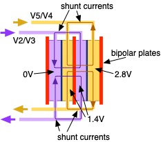
There are approaches where people have passed "protective" currents through the manifold to cancel out the shunt currents, but it is an active control method if I understand correctly.
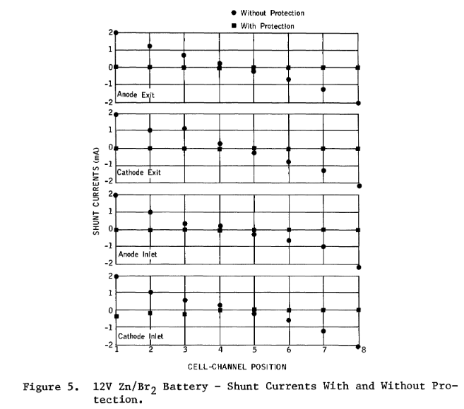
The shunt current protective currents were then passed through the protective electrodes inserted at the first and last channel/manifold node point connections. The shuntage currents through the channels were reduced/eliminated. The effects with the passage of protective current for a charge mode are shown in Figure 5. Similar data at other conditions are given in Zahn, Grimes, and Bellows, 1980.
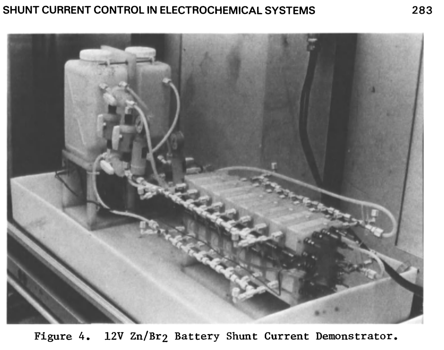
Source: White, R.E. (1984). Electrochemical Cell Design, Springer US, Boston, MA
Chapter: SHUNT CURRENT CONTROL METHODS IN ELECTROCHEMICAL SYSTEMS - APPLICATIONS
Patrick G. Grimes and Richard J. Bellows
Advanced Energy Systems Laboratory
Exxon Research & Engineering Company Linden, New Jersey 07036 -
 K kirk referenced this topic on
-
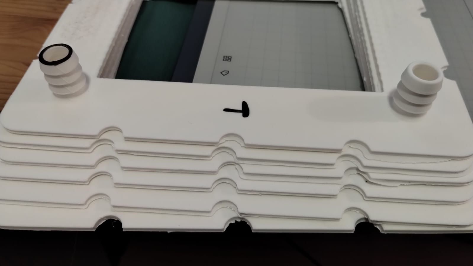
Just wanted to say I've made the first successful flow test of the large scale system. Kirk modified the flow frames to a much more simplified design for the flow path, which greatly reduced pressure and allowed flow without leaking. You can see the simpler flow path in the image below. Barbs were also added to the entry ports to prevent leaks around the hose due to pressure. Both flow frames printed water tight on my Prusa Core One.
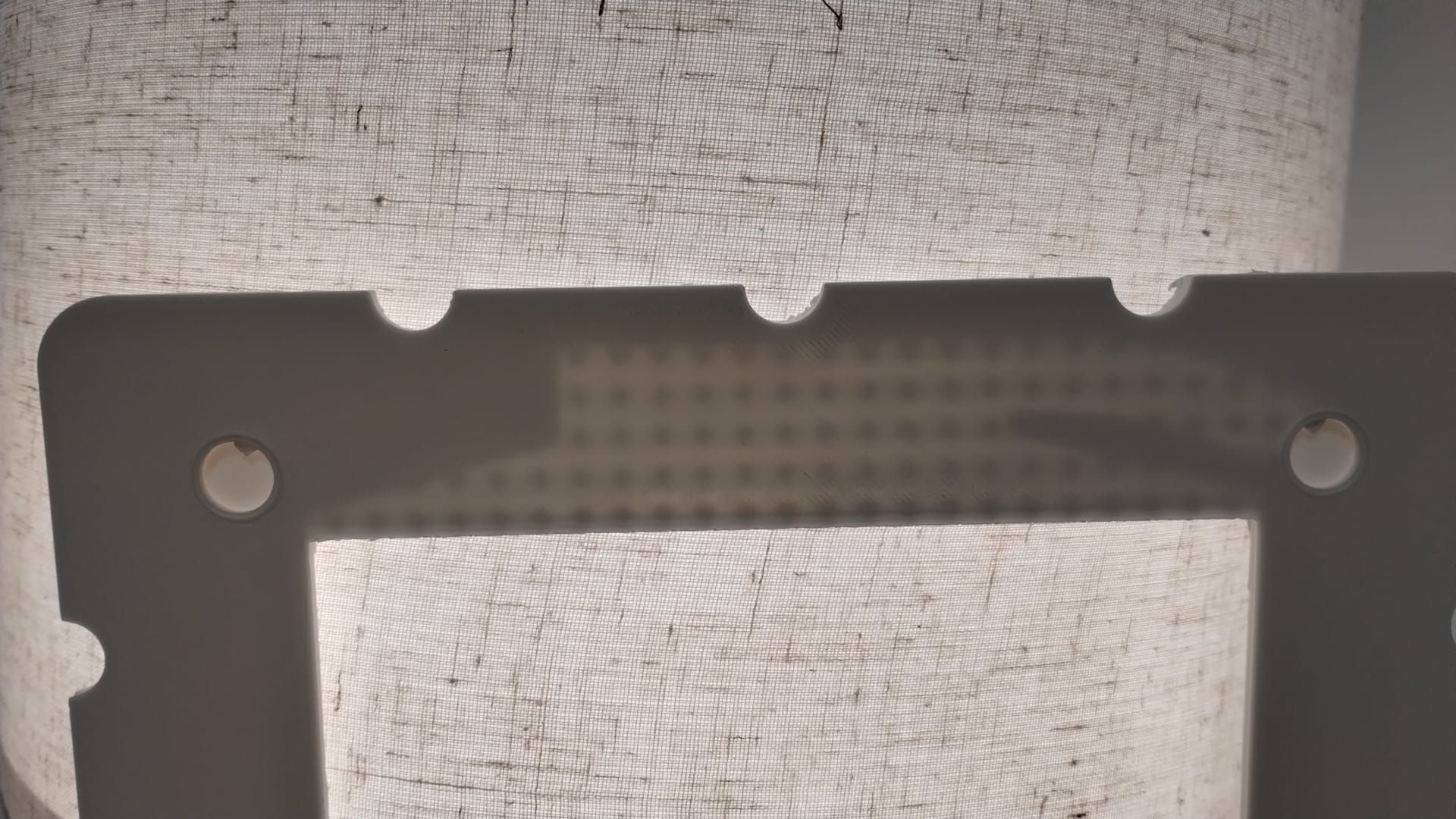
For the first test I used a single pump and flowed tap water through both chambers. I used 4 layers of photopaper as a membrane material.
I tightened everything by hand and was actually missing washers on the backside (forgot to order enough, lol). Test went well, with over 30 minutes of flow at 5-10L/min with no leaks. At very high flow ~40L/min, I did start to see some leaks through the 0.1mm silicone gasket due to overpressure. With that said, this flow rate is extremely high, ready far above anything that we would ever need and was just a stress test.
For future reference I attach the configuration file used for these prints. large_scale_flowframe_config.txt
This is the filament I normally use https://www.smartmaterials3d.com/pp-filamento#/25-color-natural/27-diametro-285_mm/239-tamano-m_650g
-
@danielfp248 Amazing! You rock! Now I wanna see this power some real world device
-
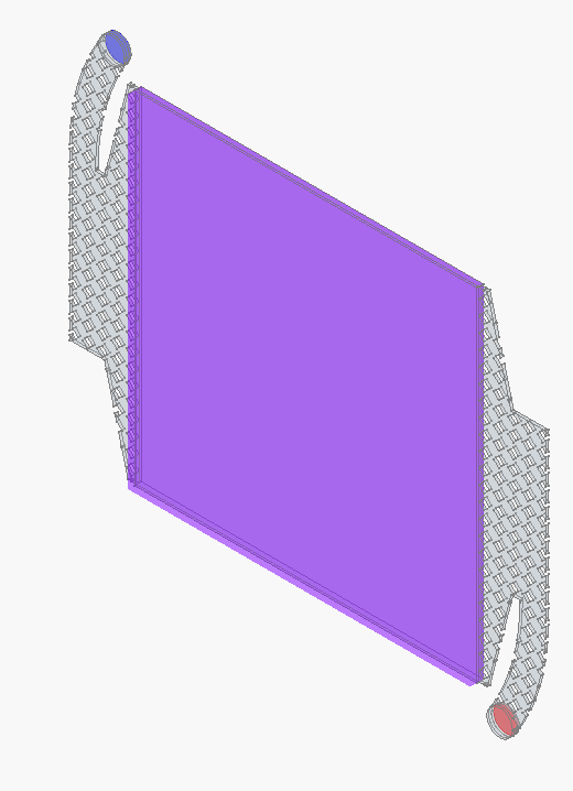
Some preliminary CFD of the simplified flow frame (U in m/s and P in Pa if I understand OpenFOAM correctly)
Conditions
- 4 L/min volumetric flowrate through one half-cell, inlet is on the top left, outlet on the lower right.
- Ambient pressure on cell outlet
- No-slip wall
- File containing CAD and CFD simulation setup is here
Blue is inlet, red outlet, pink is porous zone
 !
!
Close-up of mesh:
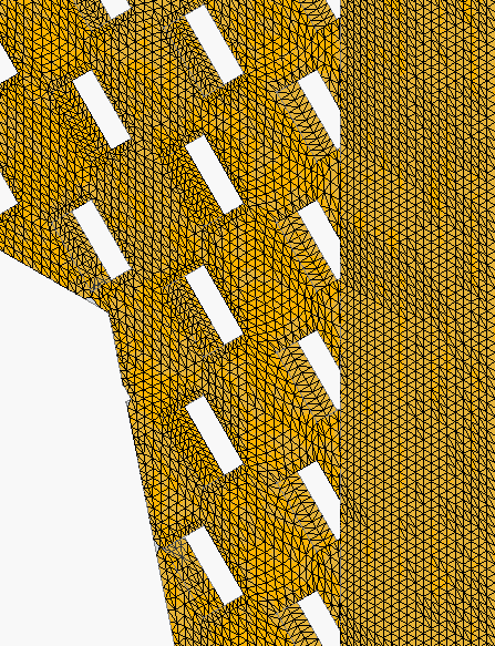
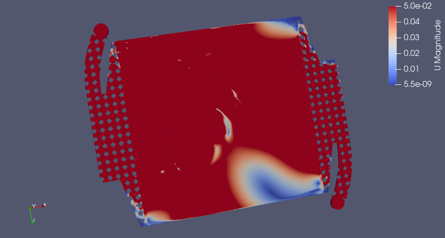
Flow Distribution (m/s)
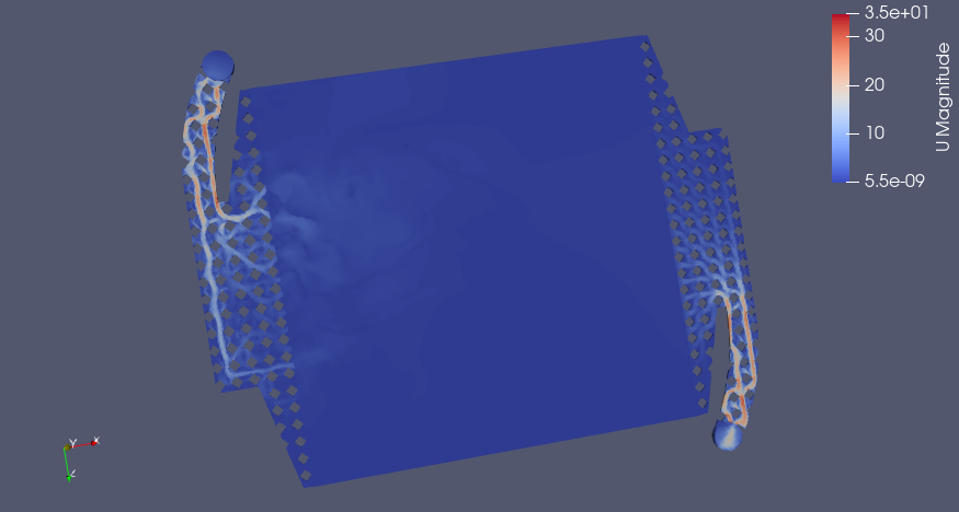
Pletcher and Walsh say a range of 0.05-0.4 m/s linear velocity is a good design range for electrolyte flow, if I apply a smaller range for velocity with 0.05 m/s as the upper limit, we see which areas in red have sufficient flow and where the dead zones are (in the corners, predictably)
Pressure Drop (Pa)

Big Caveat
Still need to calculate the Darcy-Forchheimer coefficients to do the porous zone simulation in the graphite felt, right now I am using the default values, which are almost certainly not correct. If anyone feels like finding that data (https://openfoamwiki.net/index.php/DarcyForchheimer). I think Antoni Forner-Cuenca's group has measured a lot on this recently. This could change the results quite a bit as far as flow distribution and pressure drop. I've mostly so far just been getting familiar with the simulation pipeline in FreeCAD --> CfdOF --> OpenFOAM --> ParaView.
Design is far from final, and I'm probably doing the CFD incorrectly, BUT it prints and doesn't leak! We will keep optimizing the flow frame later.
-
Hey! This is incredible work. I noticed you guys are exploring the shunt current/pressure drop/residence time distribution issue of manifold design. This is well outside my expertise, but I did run into this paper a while back from Kyle Smith, who offered a manifold design (and methodology) to resolve at least the pressure drop/residence time issue. Here's the paper - let me know if you have trouble accessing it and I'm happy to send it along.
They use a tapered header channel with straight diffuser channels and achieve very even flow rate distributions (at Reynolds numbers < 10)
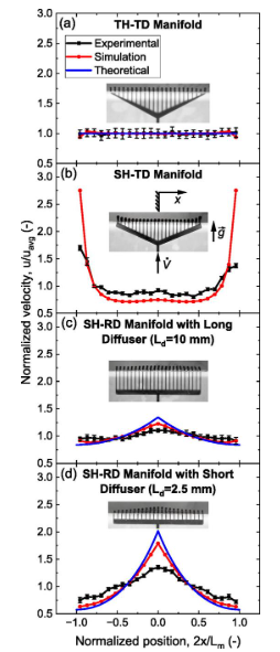
Not sure how well this prevents shunt currents but I hope this helps.
-
Hey! This is incredible work. I noticed you guys are exploring the shunt current/pressure drop/residence time distribution issue of manifold design. This is well outside my expertise, but I did run into this paper a while back from Kyle Smith, who offered a manifold design (and methodology) to resolve at least the pressure drop/residence time issue. Here's the paper - let me know if you have trouble accessing it and I'm happy to send it along.
They use a tapered header channel with straight diffuser channels and achieve very even flow rate distributions (at Reynolds numbers < 10)
Not sure how well this prevents shunt currents but I hope this helps.
@muntasirms oh this looks great, I hadn't seen the paper! It's exactly what we need for the non-shunt-current related issues (which are another bridge for us anyway, down the road). An efficient manifold seems like it could be decoupled from the shunt current protection scheme also. I will try to implement it in FreeCAD.
-
Quick video of Daniel's leak test: https://spectra.video/w/bSYUyYpJVr34N92261cd6K
-
Out of curiosity, how are you guys attaching the tubing to the cell stack? are they glued on? hose barbs? Threaded piping?
I ask because leaks are my bane in a lot of my lab setups, even with super tight bolts and threaded fittings. I'm impressed at how well you guys have managed with flexible tubing!
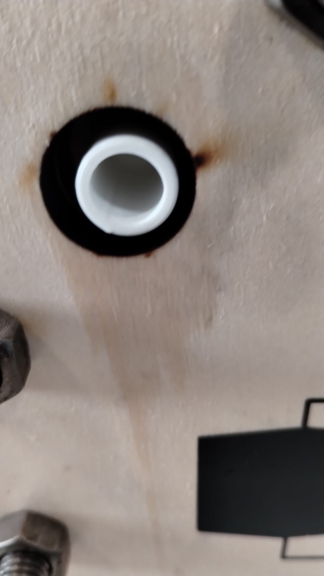
@muntasirms They are just barbed fittings. These have worked surprisingly well at both scales.
-
Some preliminary CFD of the simplified flow frame (U in m/s and P in Pa if I understand OpenFOAM correctly)
Conditions
- 4 L/min volumetric flowrate through one half-cell, inlet is on the top left, outlet on the lower right.
- Ambient pressure on cell outlet
- No-slip wall
- File containing CAD and CFD simulation setup is here
Blue is inlet, red outlet, pink is porous zone
!
Close-up of mesh:
Flow Distribution (m/s)
Pletcher and Walsh say a range of 0.05-0.4 m/s linear velocity is a good design range for electrolyte flow, if I apply a smaller range for velocity with 0.05 m/s as the upper limit, we see which areas in red have sufficient flow and where the dead zones are (in the corners, predictably)
Pressure Drop (Pa)
Big Caveat
Still need to calculate the Darcy-Forchheimer coefficients to do the porous zone simulation in the graphite felt, right now I am using the default values, which are almost certainly not correct. If anyone feels like finding that data (https://openfoamwiki.net/index.php/DarcyForchheimer). I think Antoni Forner-Cuenca's group has measured a lot on this recently. This could change the results quite a bit as far as flow distribution and pressure drop. I've mostly so far just been getting familiar with the simulation pipeline in FreeCAD --> CfdOF --> OpenFOAM --> ParaView.
Design is far from final, and I'm probably doing the CFD incorrectly, BUT it prints and doesn't leak! We will keep optimizing the flow frame later.
@kirk Had a few thoughts that I hope are helpful or probing at least. Disclaimer, fluids are not my strength. I'd be happy to hear more about your insights or goals here.
Colleague pointed out to me that there are correlations for different porous media geometries (e.g., see Fig 4 & Equation 2.6 and a bit more surrounding context in this paper for details https://link.springer.com/article/10.1007/s11242-020-01423-y). So if you have the permeability (and make some assumptions), you can have some bounded estimates of the coefficient.
I'm trying to digest the utility of the Forchheimer part of Darcy-Forchheimer. For a first-pass estimate of pressure drop, I'm willing to bet using Darcy's law is sufficient to approximate pressure drop (maybe the computational expense is smaller, and it's more instructive for a general audience IMO).
Regarding flow distribution: relating flow to performance I think will be challenging (there could be a lot of cell performance that is determined by other electrode complexities beyond whatever "inertial flow" does to transport of active species).
I'd also note that measuring the pressure drop directly could be relatively easy. We've done them with cheap pressure sensors such as these before: link. Maybe that could be of use and might be a way to check for inertial effects?
In any case, excited for the next steps in the modeling!
-
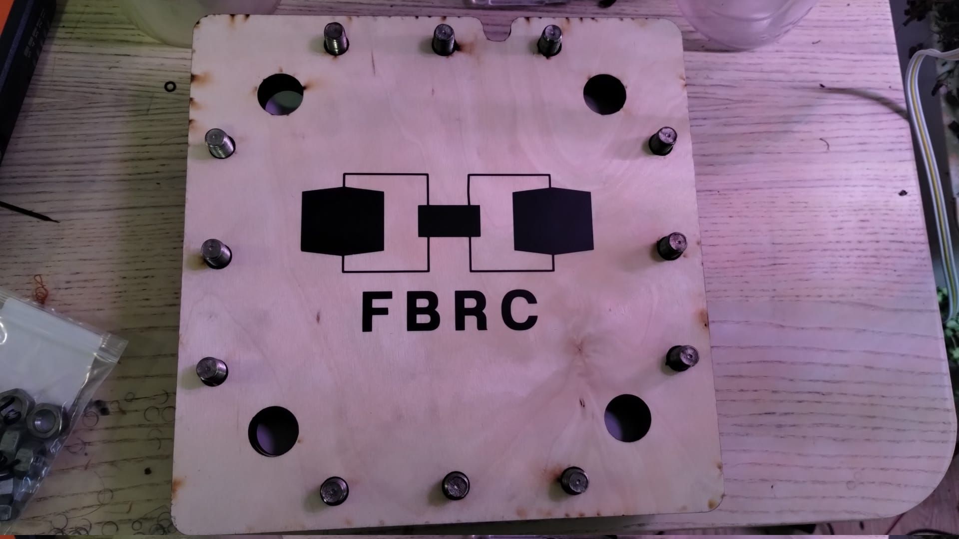
I'm finishing printing of the flowframes necessary for building the first stacked implementation. This will be a battery with three stacked cells. Each stack takes around 6mm of thickness. These are the files you have to print if you want a stacked implementation:
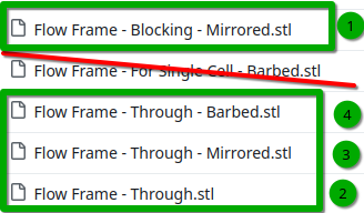
First would be blocked, then on top of that alternating through/mirrored as many times as you wish and then finally barbed at the end. For a 1kWh battery using Zn-I you would need 40 cells, so a total thickness of 24cm. I will start with a 3 cell stack, which will have a total thickness of around 2cm (counting current collectors).
-
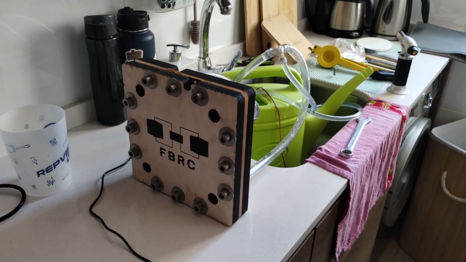
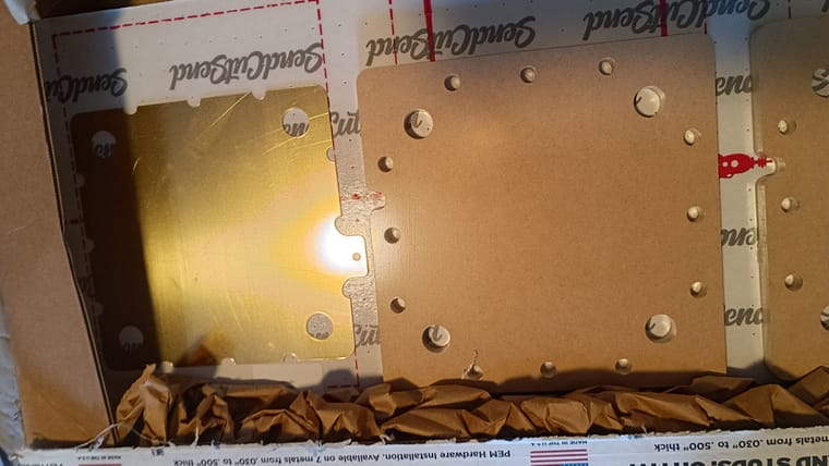
All flow frames are ready now. I'll have to wait a couple of weeks for some graphoil to cut the bipolar plate material that goes between the cells. Picture of the 6 finished flow frames below. I won't be running this with any active material, as I have no place to safely do so, I will just be testing for leaks to test the basics of the stacked design.
If ran with active material the expected voltage of this system with Zn-I would be ~3.6V and the current needed to charge it in a reasonable time would be around 3.5A. The system would produce around 12.6W, power capacity would be around 60Wh, would require around 1.5L of catholyte and 1.5L of anolyte. This would be enough capacity to run a raspberry pi for 12 hours.
Hello! It looks like you're interested in this conversation, but you don't have an account yet.
Getting fed up of having to scroll through the same posts each visit? When you register for an account, you'll always come back to exactly where you were before, and choose to be notified of new replies (either via email, or push notification). You'll also be able to save bookmarks and upvote posts to show your appreciation to other community members.
With your input, this post could be even better 💗
Register Login