Build-a-Batt - A fully parameterized flow cell stack model
-
Hi folks,
Over a couple weekends, I've been working on parameterizing the FBRC model. It was borne of a couple kinks I ran into - I would want to adjust bolt or hose barb diameters based on what I had lying around, or scale the model down for smaller lab scale setups while maintaining control over electrode thickness for lab experiments. The idea is to adjust a single parameter in a script, which then adjusts the appropriate dimension in all the design files, then spits them out for fabrication.
The result is a single "model" with flexibility to adapt plumbing, sizing, and construction according to your particular application. So for example, the same parameterized model can spit out
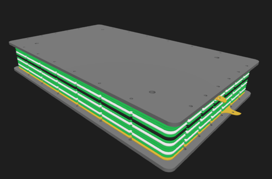
a small cell with hose barbs for lab scale applications (18cm2 electrode area)
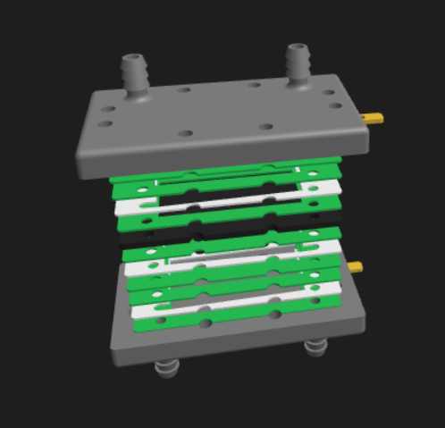
a medium size cell (using the current FBRC large format sizing)
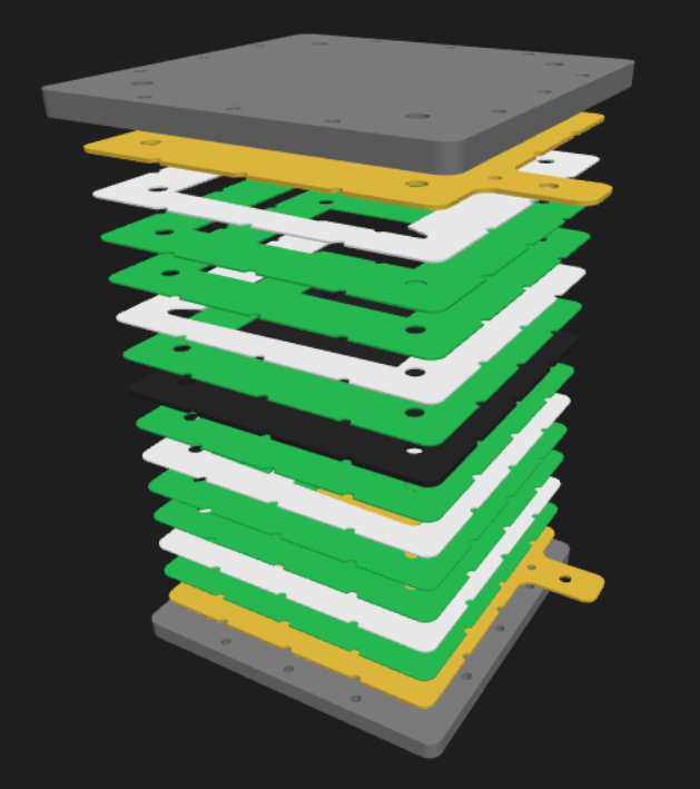
or a "fat stack" (3500cm^2) with extra, thicker bolts
all from the same parameterized design. Once the designs are generated, all the associated STL, STEP, and DXF files can be downloaded for fabrication.
If this is of any interest to you, I'm hosting the parameterized model in a webapp here and I've uploaded a short video walking through the general process here.
I briefly discuss it in the video, but because the models are parameterized, it's easier to programmatically keep track of the locations of ports, walls, manifolds, etc. That makes boundary condition declaration and the like much easier to automate as well - so I'm in the process of slotting this into an automated hydraulics/electrochemical simulation suite. Imagine generating your custom model and simulating a "digital twin" for estimates of performance prior to purchasing materials or finalizing design.
I'm very open to constructive criticism on any part of the project (from ideation to UX to engineering). Have fun fiddling with it and let me know what you think!
-
@muntasirms Muntasir, this is awesome! Sorry for the delay in getting back to you, I've just watched your walkthrough video today. The webapp loads for me but the viewport is empty? At least on a few different browsers it seems.

I watched the walkthrough though, very nice work! It looks very clean, would be awesome actually to have a 3D interface like this on the FBRC homepage, to make it a bit cooler like the https://www.open-quantum.org project.
It would be great to share the code as open-source as well, I am not familiar with the build123d library and would like to see how you've done it.
I have also been working on some automated exports from FreeCAD, to enable some CI/CD on our documentation, but nothing web-facing: https://codeberg.org/FBRC/RFB-dev-kit/src/branch/clampable-cell/CAD/FreeCAD/FreeCAD-exports.py
@muntasirms said in Build-a-Batt - A fully parameterized flow cell stack model:
That makes boundary condition declaration and the like much easier to automate as well - so I'm in the process of slotting this into an automated hydraulics/electrochemical simulation suite. Imagine generating your custom model and simulating a "digital twin" for estimates of performance prior to purchasing materials or finalizing design.
The FreeCAD models are also fully parameterizable, and can at least automatically update in the CfdOf workbench, but the whole thing in Python would be easier to handle for hardcore simulation, with any echem phenomena. This would be really cool, I would love to see you tackle some simulation/flow frame optimization! I have my hands full currently so I'm not sure when I'd get around to it.
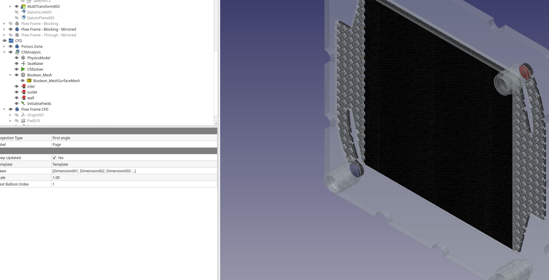 Screenshot of the flow-frame file showing the OpenFoam CFD setup.
FYI, we still haven't actually done cycling experiments with the "large-format" 175 cm2 cell, so the design is mostly likely going to change somewhat!
I am not sure the small cell (18 cm2) design you show would seal also - we did a lot of testing with that sort of approach early on and it was hard to print the chemical resistant barbed fittings and endplates in one piece, which is why we separated it out in the dev kit.
@muntasirms said in Build-a-Batt - A fully parameterized flow cell stack model:
or a "fat stack" (3500cm^2) with extra, thicker bolts
I love it! I really hope we can get here one day
 we will certainly need all hands on deck to do so.
@muntasirms said in Build-a-Batt - A fully parameterized flow cell stack model:
I'm very open to constructive criticism on any part of the project (from ideation to UX to engineering). Have fun fiddling with it and let me know what you think!
Really happy that you've kicked this off, it shows whats possible in this space. Right now, I will be sticking to FreeCAD for prototyping and derisking - I'm much faster in a graphical CAD environment implementing design changes than in a code-based CAD approach. But I think the two are complementary - especially for simulation and customization.
There was actually a project that allowed for in-browser editing of FreeCAD files in a way sort of similar to your web app - a startup called Ondsel (now out of business) that made some contributions to FreeCAD source. They had a cloud tool called Lens that allowed you to build this sort of webapp directly from the FreeCAD file by exposing certain parameters. When they shut down they gave everything to FreeCAD, it looks like the Lens project is still going and you can host it yourself: https://freecad.github.io/lens-docs/
This might be a way to combine your customization approach directly with the FreeCAD source files? I would be a fan of this approach if we could link everything as closely as possible.
For UX: would be great to have a dropdown or similar to select templates for different standard configs, like the small cell/FBRC large-format/fat stack, etc.
-
 K kirk@social.coop shared this topic on
-
Also, this reminds me of the OpenAFPM project - they also use FreeCAD and provide a dashboard for people to input custom parameters for a small wind turbine generator, there is some FEM, and then design files are output. There is a video demo here: https://www.openafpm.net/cad-visualization
I know a few of the folks behind that project, I'm sure they'd be happy to give input on how to accomplish a similar goal but for flow batteries.
Hello! It looks like you're interested in this conversation, but you don't have an account yet.
Getting fed up of having to scroll through the same posts each visit? When you register for an account, you'll always come back to exactly where you were before, and choose to be notified of new replies (either via email, or push notification). You'll also be able to save bookmarks and upvote posts to show your appreciation to other community members.
With your input, this post could be even better 💗
Register Login