Following your documentation – feedback & questions
-
Hello everyone! It’s been a while

I’ve returned to testing the flow cell and even built a second one to check repeatability. I’m wondering what could cause such a large difference in performance between them. The second cell showed only 0.85 V during discharge (compared to 1.15 V for the first one).There was also a warning during the discharge of the first (better) cell:
“The command b'RANGE 2' resulted in an unexpected response. The expected response was ‘OK’; the actual response was ‘WAIT’.”
After closing this warning and restarting the charge/discharge cycles, the system no longer stopped charging the cell at 10 mAh as before. I manually stopped the cycle at 22 mAh.
The cell was left in the workshop, and I was remotely connected from home to the Raspberry Pi controlling the pumps and Mystat. The next day, when I returned to the workshop, both tubes from the pumps had detached from the cell, and the electrolyte had spilled on the table.
Do you have any idea what might have happened?I also wanted to ask whether you’ve tried different gasket materials—such as FKM (Viton) rubber or expanded PTFE (ePTFE)?
-
@gus afaik, the firmware from kirks repo with the python mystat application is not actually the latest one (it's missing the extended range). Check the updated page on the mystat docs: https://fbrc.codeberg.page/rfb-dev-kit/pstat.html which links to thw correct version. I'm not 100% sure if that is the issue you are encountering but it might be.
Concerning the detached tubing, I could imagine the felt getting clogged somehow leading to an ovepressure making the tubes pop off. I'm having some issues with gas being pulled into one container, leading to pressure buildup in the container. I have no clue yet where this comes from.
Good luck with your further investigations! You might want to rzun your future experiments in a transparent PP box in the future. I will for sure once I'm ready for actual electrolyte.
-
Hello everyone! It’s been a while
I’ve returned to testing the flow cell and even built a second one to check repeatability. I’m wondering what could cause such a large difference in performance between them. The second cell showed only 0.85 V during discharge (compared to 1.15 V for the first one).There was also a warning during the discharge of the first (better) cell:
“The command b'RANGE 2' resulted in an unexpected response. The expected response was ‘OK’; the actual response was ‘WAIT’.”
After closing this warning and restarting the charge/discharge cycles, the system no longer stopped charging the cell at 10 mAh as before. I manually stopped the cycle at 22 mAh.
The cell was left in the workshop, and I was remotely connected from home to the Raspberry Pi controlling the pumps and Mystat. The next day, when I returned to the workshop, both tubes from the pumps had detached from the cell, and the electrolyte had spilled on the table.
Do you have any idea what might have happened?I also wanted to ask whether you’ve tried different gasket materials—such as FKM (Viton) rubber or expanded PTFE (ePTFE)?
@gus said in Following your documentation – feedback & questions:
I’ve returned to testing the flow cell and even built a second one to check repeatability. I’m wondering what could cause such a large difference in performance between them.
Hey, welcome back! As sepi said, please upload the correct firmware to the MYSTAT as an outdated version was previously present in the repo, also be sure to recalibrate your MYSTAT before cycling again, this is likely the source IMO. It wouldn't be bad to add some sort of calibration reminder/routine into the MYSTAT software...
@sepi said in Following your documentation – feedback & questions:
Good luck with your further investigations! You might want to rzun your future experiments in a transparent PP box in the future. I will for sure once I'm ready for actual electrolyte.
Definitely a good idea!
@gus said in Following your documentation – feedback & questions:
The next day, when I returned to the workshop, both tubes from the pumps had detached from the cell, and the electrolyte had spilled on the table.
Do you have any idea what might have happened?Ah shoot, sorry to hear this. I suspect if the MYSTAT was out of calibration it may have caused issues with the cycling. An issue with the iodide-containing chemistries is possible clogging of the felts with iodine if something goes wrong; normally the triethylene glycol should prevent this by forming a soluble complex, but it's possible your system got outside the normal operating range. I'd try again fresh (in a PP box/spill tray/secondary containment), with a calibrated MYSTAT running the latest firmware. Tagging @danielfp248 in case he has any suggestions.
-
Hi everyone,
Over the past few months I've started tests multiple times. In some cases, leaks appeared within the first 5 charge cycles when charging to 10 mAh at 20 mA. However, if the system was leak-free at the beginning, it would usually survive the subsequent charge cycles as well. Unfortunately, I have never managed to reach 100 mAh while charging at 40 mA, following the guidelines you provided.Each time, the voltage reached 1.65 V much earlier than expected (on average around 40 mAh). Leaks occurred frequently (tubing burst, the cell lost its seal, and once the electrolyte even suddenly leaked from the tanks(!)). On the voltage plots, these leaks showed up as sudden spikes or unstable/uneven charging voltage values. I suspect that something was often getting clogged in the system, causing a rapid pressure increase. I measured that Kamoer KPK200 pumps can generate over 0.4 MPa (!) of pressure when the outlet is blocked.
There were also attempts where I did not observe a visible leak — but even then, a one-off voltage disturbance still occurred. In those cases, the voltage began rising faster, and shortly after that it still hit 1.65 V, stopping the charge. My MyStat is calibrated, and I additionally verified the charging voltage with a multimeter to confirm it was definitely 1.65 V.
For most of my tests I used a membrane made of 3 layers of photo paper, as suggested by @kirk . Recently, I also tested a 4-layer photo paper membrane. In that setup, the charging voltage was immediately about 0.1 V higher, and it also reached 1.65 V at just under 40 mAh, stopping the charge.
I assume that in your setups you can repeatedly charge to 100 mAh at 40 mA without issues. And 100 mAh doesn’t seem like much when compared to the results in this publication https://www.nature.com/articles/ncomms7303 , where the authors reported 166.7 Wh/L. For an FBRC cell, that would correspond to roughly 1200 mAh, correct?
Do you have any advice for me? Where could the root cause of my failures be?
Am I definitely not supposed to use polypropylene felt on the catholyte side?
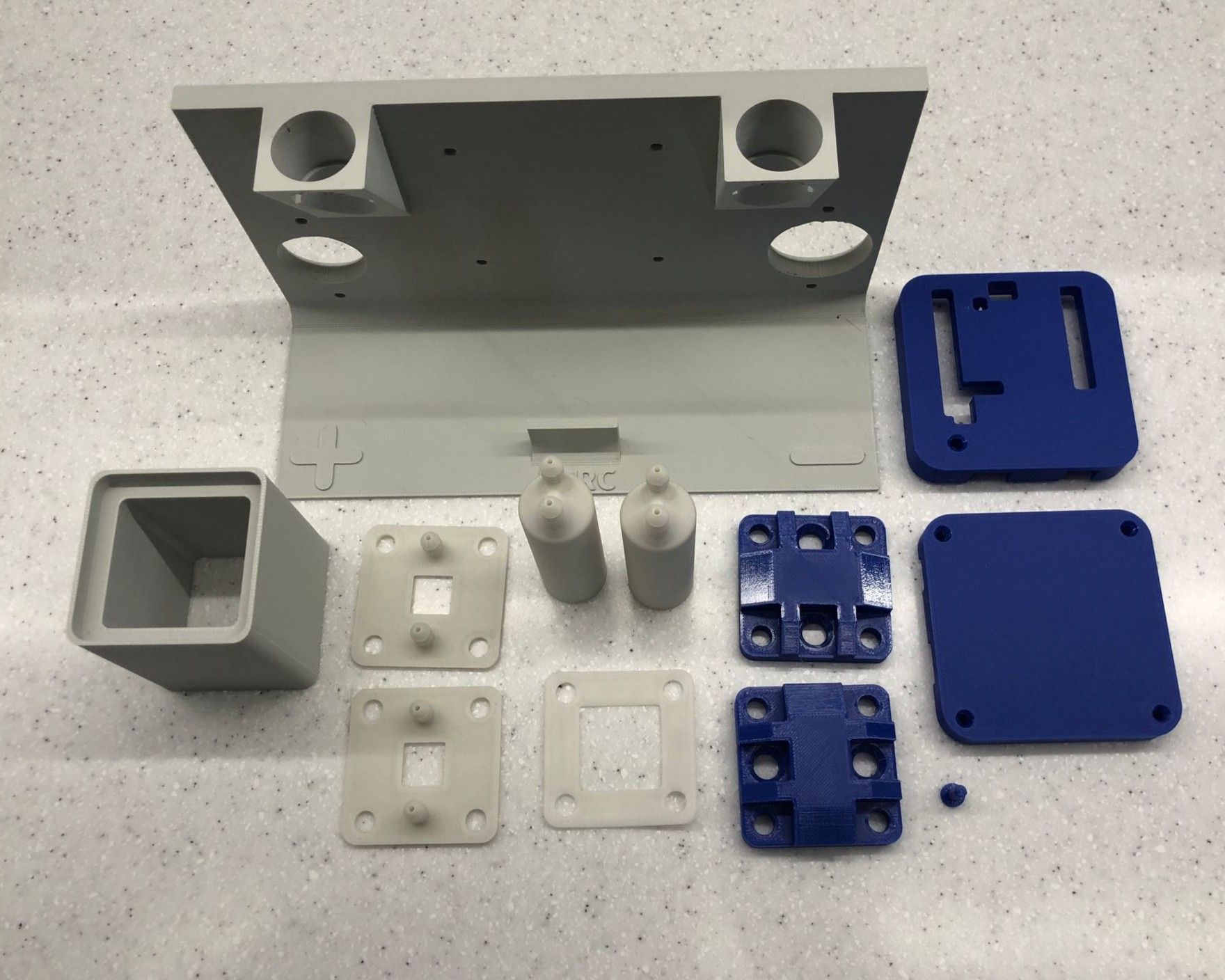
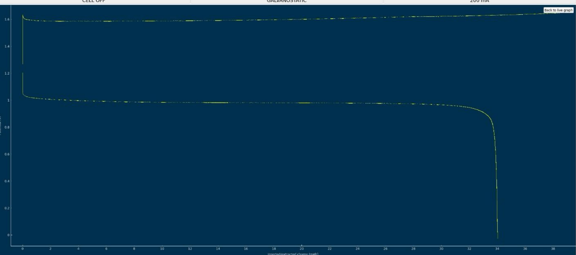
Could there be an issue with the material quality I'm using (even though everything was purchased according to the Bill of Materials sources)?Pasting results from my latest run below — the 4-layer photo paper membrane test, charging current 40mA.
-
Hi everyone,
Over the past few months I've started tests multiple times. In some cases, leaks appeared within the first 5 charge cycles when charging to 10 mAh at 20 mA. However, if the system was leak-free at the beginning, it would usually survive the subsequent charge cycles as well. Unfortunately, I have never managed to reach 100 mAh while charging at 40 mA, following the guidelines you provided.Each time, the voltage reached 1.65 V much earlier than expected (on average around 40 mAh). Leaks occurred frequently (tubing burst, the cell lost its seal, and once the electrolyte even suddenly leaked from the tanks(!)). On the voltage plots, these leaks showed up as sudden spikes or unstable/uneven charging voltage values. I suspect that something was often getting clogged in the system, causing a rapid pressure increase. I measured that Kamoer KPK200 pumps can generate over 0.4 MPa (!) of pressure when the outlet is blocked.
There were also attempts where I did not observe a visible leak — but even then, a one-off voltage disturbance still occurred. In those cases, the voltage began rising faster, and shortly after that it still hit 1.65 V, stopping the charge. My MyStat is calibrated, and I additionally verified the charging voltage with a multimeter to confirm it was definitely 1.65 V.
For most of my tests I used a membrane made of 3 layers of photo paper, as suggested by @kirk . Recently, I also tested a 4-layer photo paper membrane. In that setup, the charging voltage was immediately about 0.1 V higher, and it also reached 1.65 V at just under 40 mAh, stopping the charge.
I assume that in your setups you can repeatedly charge to 100 mAh at 40 mA without issues. And 100 mAh doesn’t seem like much when compared to the results in this publication https://www.nature.com/articles/ncomms7303 , where the authors reported 166.7 Wh/L. For an FBRC cell, that would correspond to roughly 1200 mAh, correct?
Do you have any advice for me? Where could the root cause of my failures be?
Am I definitely not supposed to use polypropylene felt on the catholyte side?
Could there be an issue with the material quality I'm using (even though everything was purchased according to the Bill of Materials sources)?Pasting results from my latest run below — the 4-layer photo paper membrane test, charging current 40mA.
@gus Thanks for writing about your experience and again for reproducing the kit!
One of the issues of the Zn-I chemistry is that I2 can easily generate if the local concentration of iodide is not high enough. This can happen due to several reasons. For example if the electrolyte is not circulated fast enough, if the state of charge is too high or if the current is too high. The triethylene glycol helps avoid this, but it also runs into a limit if the right circumstances happen.
The electrolyte we suggest for testing is 2M I and 1M Zn. The max expected capacity of this electrolyte would be 17.6Ah/L, which our setup (if you use 5mL per side) would be around 176mAh. The 166Wh/L value from the paper you quote has to be interpreted carefully. First, consider that this value is measured in a 5M ZnI2 electrolyte, which is 10M I2, it is 5x as concentrated as the electrolyte we use. Second, this value reported on the paper is accounting for the catholyte volume only, so the actual total Wh/L has to be divided by 2 to compare with the values above, so it would be 83Wh/L. For our electrolyte 5x more concentrated we would expect to get 88Ah/L (105Wh/L at a voltage of 1.2V) which would be higher than the paper you cited, because we indeed expect to extract more capacity because of the use of triethylene glycol.
With that said, Zn-I is a hybrid battery (as you plate a metal) so the mAh/cm2 is also important. If you plate too much Zn not only do you get Zn dendrites but the setup will also clog because of the metal deposition process clogging the felt. The paper you cite uses a cell with an area of 40cm2 but the volume of electrolyte is never disclosed, so we don't know how much they plated in terms of mAh/cm2. However, other Zn-I literature suggests we shouldn't attempt to go above 100mAh/cm2, the lower the safer. For this paper I suspect this value was below the 10mAh/cm2 mark because of the lack of dendrites and the thickness of the membrane. This however means that in our system at 2cm2 we shouldn't charge above 200mAh, so even if we increased electrolyte concentration our max capacity is going to be limited to around 20Ah/L, perhaps we can push this to 26-30Ah/L by reducing volume, but I'm afraid not much more beyond that.
The membrane is another key point. The nafion membranes typically used are much lower resistance and much higher conductivity than a membrane like photopaper. While photopaper works well for demonstrating the cell, its resistance is going to be much higher and therefore our energy efficiencies and current densities will be much lower. If you contact me by chat I can mail you some daramic, which is a commercial microporous membrane, so that you can test it out and get better capacities. Another alternative is to modify photopaper (for example with PVA) to be able to use a single layer.
To answer your questions:
Do you have any advice for me? Where could the root cause of my failures be? - I wouldn't call your results a failure! I think you're doing well. Your charge/discharge curve looks great. You can try the following things:
- Try decreasing your current to 20mA and see if this way you can charge to the higher SOC, this will show if the problem is just your current density and transfer speeds.
- Also you can try activating your felt by putting it in commercial bleach for 48 hours, then washing it with distilled water thoroughly before using it. This improves the wetting of the felt a lot and helps the kinetics of the electrochemical reactions.
- Decrease your volume per side to 4mL, this will reduce the mAh/cm2 which will make clogging less likely as the SOC climbs.
Am I definitely not supposed to use polypropylene felt on the catholyte side? You get best results without polypropylene on either side. Change to felt on both sides to get better SOC values. We also never used it on the catholyte side only on the anolyte side. If you use nonconductive felt on both sides you will reduce the chances of clogging but your energy efficiency will be dramatically lower.
Could there be an issue with the material quality I'm using (even though everything was purchased according to the Bill of Materials sources)? I don't think so, if you got everything from the BOM, then everything should be the exact same I have.
Let me know how things go!
-
Oh, I didn’t realize the 166 Wh/L value was referenced only to the catholyte, so thanks @danielfp248 for pointing that out.
In the meantime, it occurred to me that maybe the ambient temperature (10–15 °C) could be a cause. What do you think?
Regarding electrolyte circulation: I use the same Kamoer KPK200 pumps, currently set to 30% on the catholyte side (just to confirm — that’s the electrolyte that turns red during operation, correct? ) and 45% on the anolyte side. I also ran the cell without using PP felt on either side.
Thanks for all the practical advice. However, I’d like to understand if there were any additional factors or preparation steps not mentioned in the build instruction? For example: activating the graphite felt, using PP felt in any configuration, or modifying the photopaper membrane?
I would like to make my cell and electrolyte work in the same “default” setup that you have already proven.
Thanks again for your time — and also for the offer to share membrane samples. I think I will be interested in testing other membranes after making the cell work reliably with photopaper first.
@gus Thanks for your reply!
Yes, low temperature is a BIG issue for this system but should be much less so with the trieg present. You can replace 5% of the water with ethanol to see if this reduces the problem.
I am also testing an alternative pump configuration that is working much better, sucking the solution through the cell instead of pushing it through (Kirk's suggestion). So the pumps push solution to the top of the reservoirs and suck it out of the cell, like on this diagram:
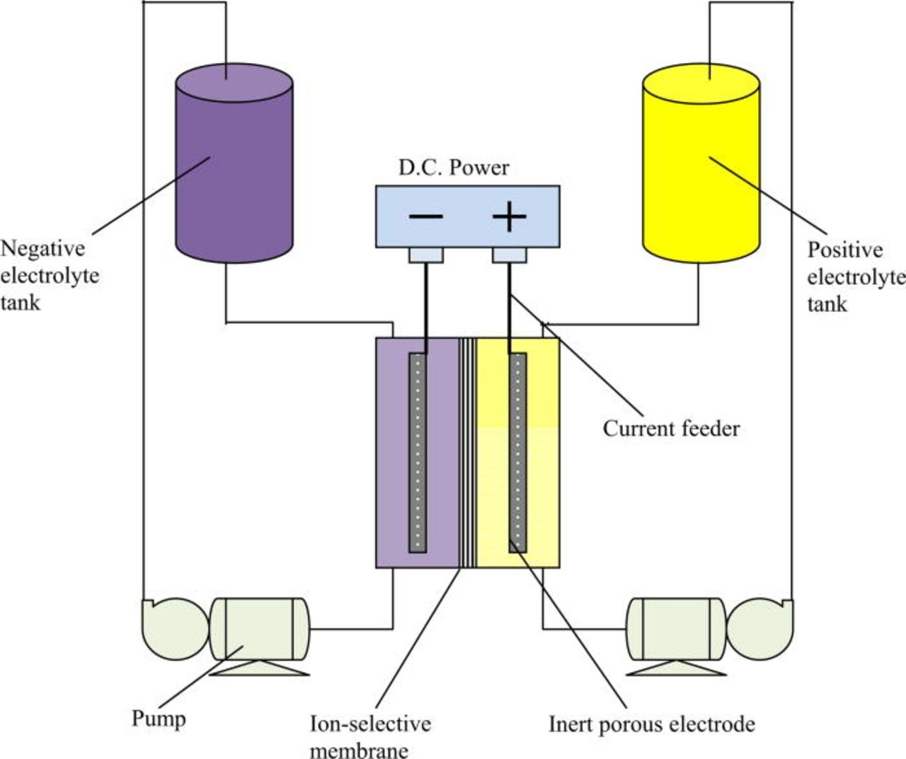
This way if the cell gets overpressured it basically stops flowing but tubing never disconnects and spills everywhere. Pumps are also much quieter in this configuration.
I will run some tests with photopaper membrane so that you can get some idea of what I can achieve at this time.
-
@danielfp248 Thanks. So I’ll wait for the results you can achieve with the same setup I’m using.
Regarding the suction-based pump configuration - I’ve been thinking about it too. Generating underpressure behind the cell would likely remove leakage issues. However, it is a more energy-consuming solution, so it doesn’t seem suitable as a final approach for a large battery system. Also, with the pumps operating in suction mode, any sealing imperfections would likely result in air being drawn into the system...
Thanks again for running the photopaper membrane tests - looking forward to the numbers.
-
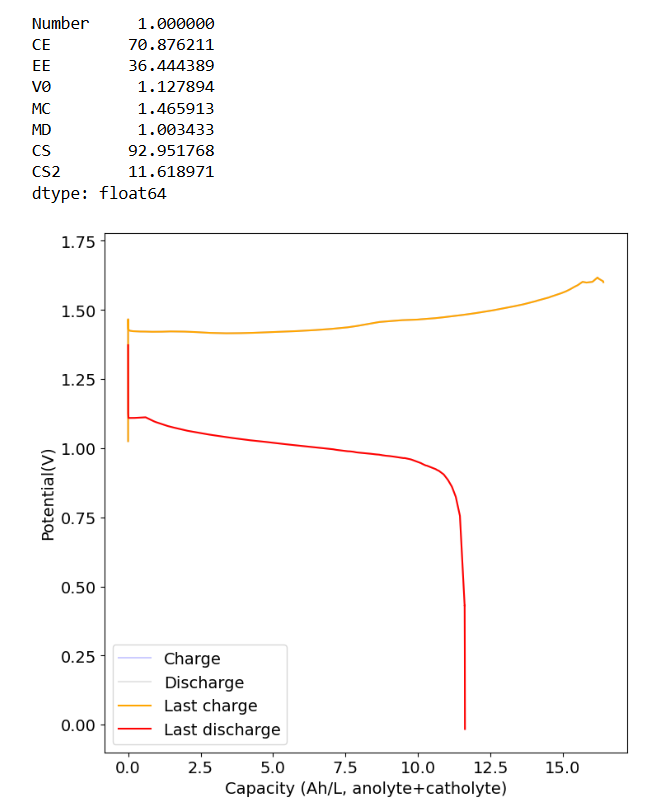
This is performance to 1.6V using the "suction" configuration and 3 layers of photopaper with carbon felt on both sides.
-
@danielfp248 Wow, that’s much more than I’ve ever been able to obtain. Did you do anything to the graphite felt or the paper membrane before using them? Did you use the default membrane frame from your documentation, or did you adjust the thickness to better fit three sheets of photo paper? What charge/discharge currents, capacities (mAh), and cycles (half-cycles) did you perform before achieving the result you posted? And what current did you use for the final charging of the cell - 40 mA or less? Are you planning to continue using pumps that generate a vacuum behind the cell, despite all the weak points of this solution?
@gus No, this was both unmodified felt and membranes. This also didn't use any membrane frame, just the photopaper compressed between the silicon gaskets. The charge discharge current was set to 40mA. Before charge/discharge I circulated electrolyte for 15 minutes. I also did 2 cycles to 10mAh at 20mA to make sure I wasn't getting any abnormal behavior.
Also, we're planning to use the suction setup from now on, the safety improvements are worth the potential tradeoffs in my opinion.
-
@danielfp248 Thanks. So I’ll wait for the results you can achieve with the same setup I’m using.
Regarding the suction-based pump configuration - I’ve been thinking about it too. Generating underpressure behind the cell would likely remove leakage issues. However, it is a more energy-consuming solution, so it doesn’t seem suitable as a final approach for a large battery system. Also, with the pumps operating in suction mode, any sealing imperfections would likely result in air being drawn into the system...
Thanks again for running the photopaper membrane tests - looking forward to the numbers.
@gus said in Following your documentation – feedback & questions:
However, it is a more energy-consuming solution, so it doesn’t seem suitable as a final approach for a large battery system.
This "pulling through the cell" configuration is only possible with peristaltic pumps on the small scale, centrifugal pumps wouldn't handle this, due to net positive suction head/cavitation issues---this approach wouldn't end up in a real, real-world system, but we're going to recommend it for now at the benchtop scale to make testing easier!
-
@danielfp248 I always performed more cycles before starting 40 mA / 100 mAh charging (10 half-cycles at 20 mA / 10 mAh + 4–10 half-cycles at 30 mA / 10 mAh). The cell was also wet with demineralized water (leakage test). Could this also be the cause? I was also always using the membrane frame. Wouldn't the electrolyte leak through the paper membrane?
@kirk Apart from solving the electrolyte leakage issue, does this "pulling-through configuration" improve the total capacity of the system in any other way? Also, I am wondering whether you are using the default flow frame from the documentation (2 mm thick, right?) or a different one with another thickness and the 0.1 mm silicone gaskets.
Hello! It looks like you're interested in this conversation, but you don't have an account yet.
Getting fed up of having to scroll through the same posts each visit? When you register for an account, you'll always come back to exactly where you were before, and choose to be notified of new replies (either via email, or push notification). You'll also be able to save bookmarks and upvote posts to show your appreciation to other community members.
With your input, this post could be even better 💗
Register Login