My build (very slowly progressing)
-
@danielfp248 Thanks for the quick and thorough answers! You should add those points to the docs unless you feel that this might potentially create legal trouble.
About the PPE, I was wearing nitrile gloves, cotton work cloths and plastic safety glasses (not closed though). I felt reasonably safe
")
About the copper carbonate for precipitation, would that be the natural one or basic one? Since I'm curious and want to bring my chemistry skills up to date: how do you know that this will cause precipitation? Is this compound used frequently for precipitation? Is this about chemical potential of copper iodide (s) and zinc carbonate (s) being lower than the sum of their respective ions (aq) in solution?
@danielfp248 Thanks for the quick and thorough answers! You should add those points to the docs unless you feel that this might potentially create legal trouble.
I think we can add these as reasonable guidelines, we will include clarification that waste disposal should always be consulted with local regulations though.
About the PPE, I was wearing nitrile gloves, cotton work cloths and plastic safety glasses (not closed though). I felt reasonably safe
That seems adequate, especially if adequate ventilation is also in place. The quantities are small, so hopefully this also reduces the risk.
About the copper carbonate for precipitation, would that be the natural one or basic one? Since I'm curious and want to bring my chemistry skills up to date: how do you know that this will cause precipitation? Is this compound used frequently for precipitation? Is this about chemical potential of copper iodide (s) and zinc carbonate (s) being lower than the sum of their respective ions (aq) in solution?
This is because Zn carbonate and Cu iodide are insoluble so a double displacement reaction occurs and both fall out of solution. There is an additional complication in that Cu+2 does oxidize I- to elemental I2, so you will also have some solid iodine formation. What precipitates is actually Cu(I) iodide. You can add some Na thiosulfate if you want to make sure all iodine precipitates as copper (I) iodide.
-
So I have gotten my pumps, off course they are the wrong ones, the brushed version and not the brushless. This creates problems since I can't easily adjust the RPMs. I instead got some c+eap PWM H-Bridge drivers to at least have some open loop control. Using this setup, I managed to do my first leak testin. As expected my homemade barbed tube connectors were not all tight and the cell leaked too. I'll try again without the connectors I added for easier cell removal. After having tightened the cell quite a bit, I think it os tight. This would need to be tested again with the aforementioned setup. So my buimd has slowed down considerably due to lack of time, but it hasn't halted :).
-
After installing tubes without my homeprinted barbs for easy removal, I managed to get the system running without a liquid leak. I've had it run for 5min with no visible leak but will let it run for an hour or so to make sure.
On the negolyte side, there is however some fizzing to be seen in the tank, also when I place the septum on the right tank, at some point it will pop off. There is thus a gas leak somewhere. Do you have a good strategy how to find this @danielfp248 @kirk ? I guess it's in the part where the liquid is sucked out of the cell and into the pump.
I managed to fix an issue with one pump running quite a bit slower than the other with equal voltage applied. I managed to trace the issue back to one for the gears in the planetary gearbox being slighly misplaced. Has anyone had those issues yet? After making sure all gears are inserted perfectly symmetrically, both pumps run pretty smoothly and less hot.
-
So I have gotten my pumps, off course they are the wrong ones, the brushed version and not the brushless. This creates problems since I can't easily adjust the RPMs. I instead got some c+eap PWM H-Bridge drivers to at least have some open loop control. Using this setup, I managed to do my first leak testin. As expected my homemade barbed tube connectors were not all tight and the cell leaked too. I'll try again without the connectors I added for easier cell removal. After having tightened the cell quite a bit, I think it os tight. This would need to be tested again with the aforementioned setup. So my buimd has slowed down considerably due to lack of time, but it hasn't halted :).
@sepi said in My build (very slowly progressing):
I have gotten my pumps, off course they are the wrong ones,
Oh shoot, that's annoying, I'm sorry to hear but they will still allow you to test.
@sepi said in My build (very slowly progressing):
I managed to get the system running without a liquid leak.
Awesome progress!
@sepi said in My build (very slowly progressing):
After making sure all gears are inserted perfectly symmetrically, both pumps run pretty smoothly and less hot.
This is a good catch, I had this happen once when I manually swapped the tubing out.
@sepi said in My build (very slowly progressing):
After more than an hour, the negolyte tank almost overflowed and the posolyte one was almost empty. This seems weird to me because both pumps seem to run at the same RPM.
This sounds like internal leakage through/around the membrane or similar, or some type of flow obstruction in one flow path that is causing higher pressure on one side of the membrane and bulk fluid transfer from one side to the other. The pressures on each side of the cell should be roughly matched, total imbalance in an hour is too fast. All your printed parts seem to have clear internal flow channels?
-
@sepi said in My build (very slowly progressing):
I have gotten my pumps, off course they are the wrong ones,
Oh shoot, that's annoying, I'm sorry to hear but they will still allow you to test.
@sepi said in My build (very slowly progressing):
I managed to get the system running without a liquid leak.
Awesome progress!
@sepi said in My build (very slowly progressing):
After making sure all gears are inserted perfectly symmetrically, both pumps run pretty smoothly and less hot.
This is a good catch, I had this happen once when I manually swapped the tubing out.
@sepi said in My build (very slowly progressing):
After more than an hour, the negolyte tank almost overflowed and the posolyte one was almost empty. This seems weird to me because both pumps seem to run at the same RPM.
This sounds like internal leakage through/around the membrane or similar, or some type of flow obstruction in one flow path that is causing higher pressure on one side of the membrane and bulk fluid transfer from one side to the other. The pressures on each side of the cell should be roughly matched, total imbalance in an hour is too fast. All your printed parts seem to have clear internal flow channels?
@kirk said in My build (very slowly progressing):
This sounds like internal leakage through/around the membrane or similar, or some type of flow obstruction in one flow path that is causing higher pressure on one side of the membrane and bulk fluid transfer from one side to the other. The pressures on each side of the cell should be roughly matched, total imbalance in an hour is too fast. All your printed parts seem to have clear internal flow channels?
That could be the culprit. When I finally find some time, I'll check if I can blow through the flow frame. An obstructed manifold would indeed explain why or gets sucked into the tanks. Thanks for the diagnostics!
-
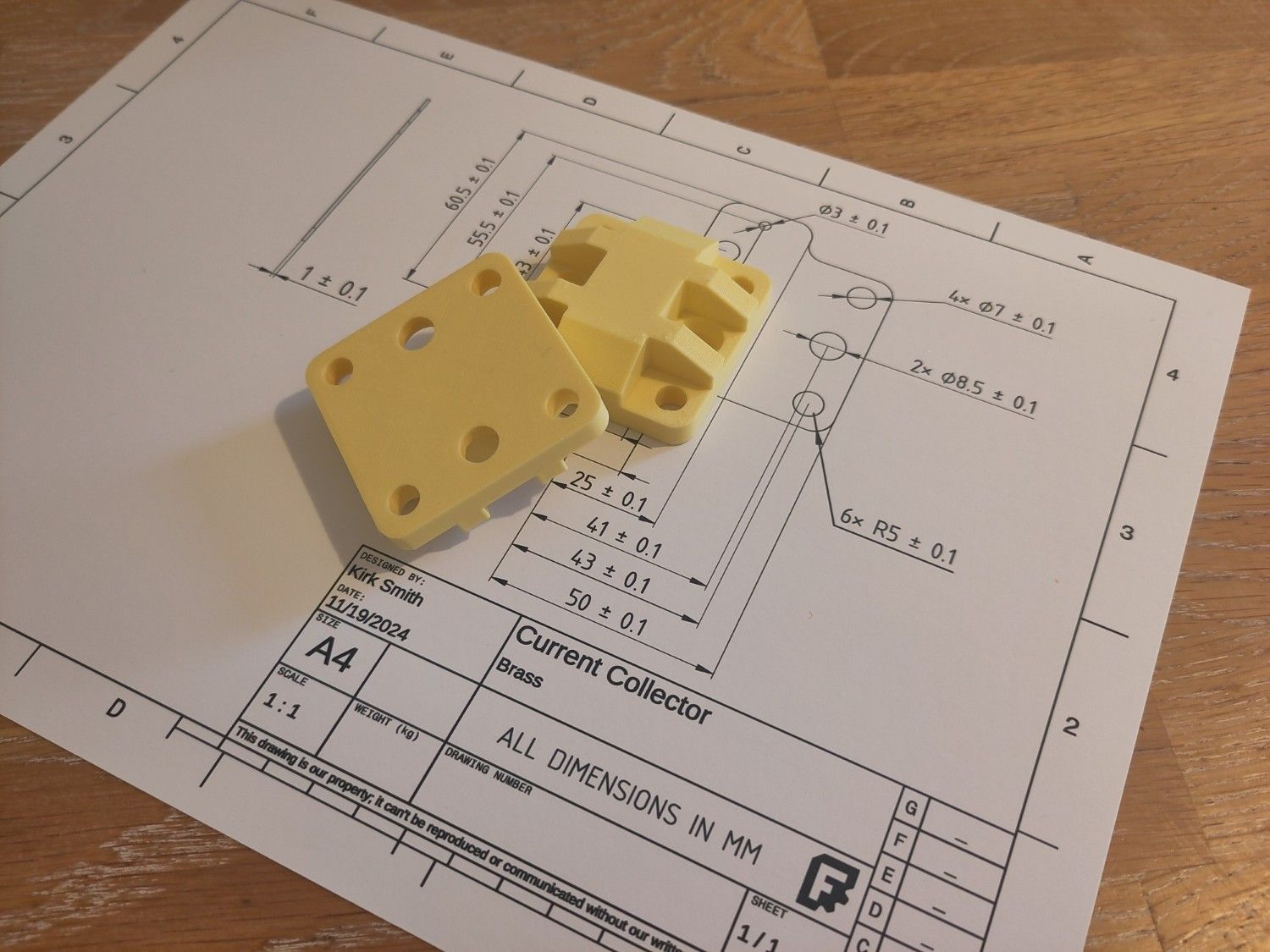
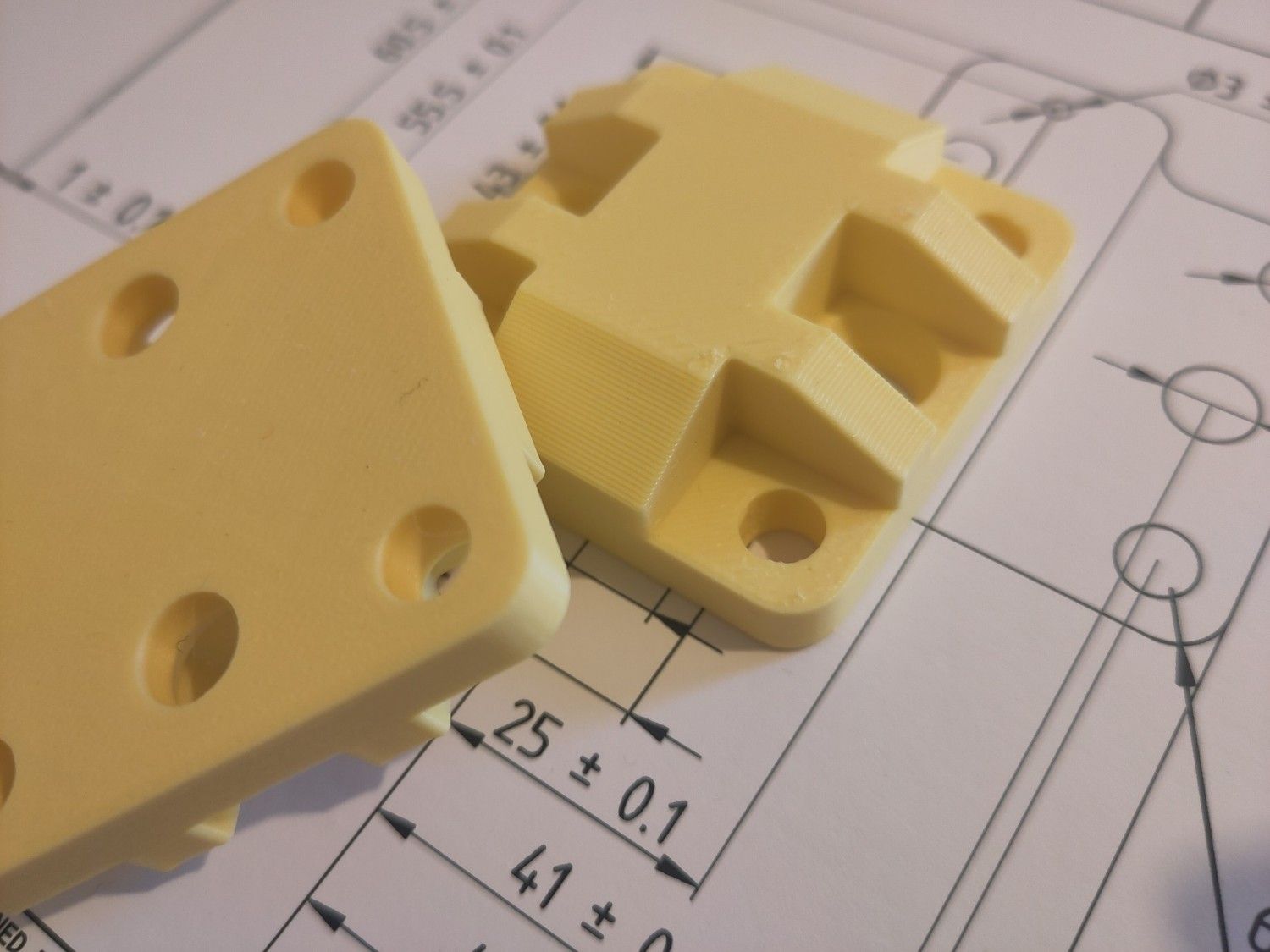
@kirk I finally found some time to advance the project. I managed to run the cell on deionised water for an hour without leakage nor bubbling or weird pressure buildup in the tanks. The issue was that one of the flow frames had a very large resistance to water flow. I guess this was some kond of print failure. Once I knew what to look for, it was very easy to diagnose by blowing through the two barbs.
I'll do some flow measurements next and then I can finally do some actual cycling. Yay!!
-
Awesome news! It's true that the FDM printed flow frames are one of the biggest wildcards in this setup. Right now it seems to be trial-and-error, in the future it would be good to have a quick go/no-go test to do right after a print, without having to assemble an entire cell.
Good luck moving forward, let us know how it goes!
-
@kirk @danielfp248 I just did some measurements of flow rate with my setup. I measured the time to pass 40ml of deionised water through one side of the cell while the other side cycles deionised water. I tested with 11V-19V and ended up with values between 40 and 120mL/min. There is quite a bit of difference between the two pumps, the left passing up to 40% more water at the same voltage. I will repeat this once I have the PWM regulator set up correctly. I'm afraid though that the pumps have issues running at lower than the 11V, especially for more visquous fluids.
My questions are:
- Is this 20-40ml/min measured with the cell in line or just the pump.
- Is the figure obtained with water or electrolyte?
- What would you recommend doing against the excess flow?
@sepi Without the four-wire control the pump speeds are definitely harder to manage, sorry to hear that, though the PWM regulator may help. Can you visually see how different the rotation speeds are? That should be rough proxy for volumetric flowrate. I am not surprised they won't spin below 11 V.
@sepi said in My build (very slowly progressing):
Is this 20-40ml/min measured with the cell in line or just the pump.
Ideally best to measure with the cell inline, to be closer to the actual conditions. However, as the tubing wears, this can drift, just FYI. Not a huge deal but something to be aware of.
@sepi said in My build (very slowly progressing):
Is the figure obtained with water or electrolyte?
Water for now, just as a proxy, minimize exposure to electrolyte. This is kind of a 1, maybe 2 significant digit measurement, no more (the volumetric flowrate).
@sepi said in My build (very slowly progressing):
What would you recommend doing against the excess flow?
@sepi said in My build (very slowly progressing):
the left passing up to 40% more water at the same voltage.
At the same voltage, is the left pump spinning at (nearly) the same rate as the right? if they are spinning at the same rotational speed and the left is passing 40% more water, it sounds like there is some flow restriction in the right pump's flow loop. If they have identical flow loops (in terms of pressure drop), and are set at the same voltage, I would guess that they should rotate at similar speeds, but this may not be the case for the brushed motors (e.g. variance in motor properties).
What is important for testing, is that both pumps are above a minimum flowrate to ensure good mass transfer, and that the pressure imbalance between the two sides isn't too great as to cause transfer of electrolyte from one side to another through the separator. If the flowrates aren't perfectly matched but those two previous conditions are met, it's not a big issue, although it's just better for repeatability for them to be the same.