Skip to content
  • Categories
  • Recent
  • Tags
  • Popular
  • Users
  • Groups
Skins
  • Light
  • Brite
  • Cerulean
  • Cosmo
  • Flatly
  • Journal
  • Litera
  • Lumen
  • Lux
  • Materia
  • Minty
  • Morph
  • Pulse
  • Sandstone
  • Simplex
  • Sketchy
  • Spacelab
  • United
  • Yeti
  • Zephyr
  • Dark
  • Cyborg
  • Darkly
  • Quartz
  • Slate
  • Solar
  • Superhero
  • Vapor

  • Default (No Skin)
  • No Skin
Collapse
Logo that says

Flow Battery Research Collective

Q

quinnale

@quinnale
About
Posts
15
Topics
1
Shares
0
Groups
0
Followers
0
Following
0

Posts

Recent Best Controversial

  • Towards a working system
    Q quinnale

    Thanks Kirk!

    Here's a brief update. I've decided to see how I can make this with the simplest of tools (i.e., thinking if one didn't have access to CNC or a manual mill).

    I've found that using hand files, drill bits, and a coping saw (24 tpi bimetal blade), I can make the current collectors of 1 mm brass with a little elbow grease (WD-40 made the cutting substantially easier). My hacksaw was not a great choice for the thin brass.

    In addition, by printing the gasket template for a guide, and then cutting the holes and cavity with some cheap circular punches and an x-acto knife, I got some jenky gaskets.

    cell_items_and_tools.png

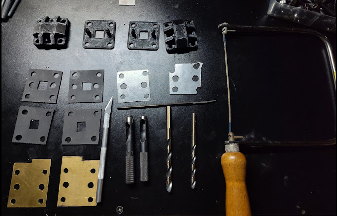
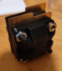
    Not the prettiest, but I'll refine my technique as needed. I'm eager to get to leak testing to see whether my printing settings are OK.

    cell_assembled.png

    Also, should I have made this a blog post? Happy to delete and move if that's better.

    General Discussion

  • Towards a working system
    Q quinnale

    components.jpg

    Inspired by Gus to share my journey. Some quite useful info in that thread. I expect my journey to be a bit more "scrappy", given I'm trying to make this work with some items I have lying around. I also might deviate on the first chemistry I test: we'll see.

    For now here's a picture of some of the components I've printed, including two peristaltic pump heads that interface with NEMA-17 stepper motors and that use bearings as the rollers. Links to them here:

    • https://www.myminifactory.com/object/3d-print-peristaltic-pump-63137
    • https://makerworld.com/en/models/497147-peristaltic-pump-\_-nema-17-\_-608-bearings#profileId-622582

    Small steps, hoping my next post is me showing whether I can get the pumps to work. I'd be curious if anyone has had success with such 3D-printed pumps. I'll try to provide some more feedback in the coming posts too.

    General Discussion

  • Connecting potentiostat
    Q quinnale

    Hi sepi, you could! I've done this with other flow cell systems. E.g., I've used one of these cheap DC power supplies and monitored the current using an INA219.

    Potentiostats are generally better-designed and have more features: good time resolution, finer potential/current control, have a reference lead, often have potential limits, and provide more-complex waveforms (like scanning potentials).

    Depending on the source, you might have to swap the leads to charge/discharge (i.e., if there is no negative bias).

    Be wary of setting the potential too high on these DC power sources or you can destroy some of the electrode materials or generate a bunch of hydrogen / oxygen.

    Again, doable, just some limitations! Hopefully I'm not forgetting any crucial ones here.

    General Discussion potentiostat documentation help

  • Towards a working system
    Q quinnale

    Also, here's an update on the 3D-printed pump! Been running it for about an hour, no issues. Unlisted Youtube video . If anyone is curious I can provide more details. Gonna try run it to death, see if the plastic or the tubing fails first.

    Oh I should I add I leak tested my cell. I noted a few issues (1) the brass current collectors got bent and didn't seal properly and (2) the ports seem to be leaking. I'll need to reprint those parts with different settings. Hopefully this weekend 🙂 .

    General Discussion

  • Towards a working system
    Q quinnale

    Small updates. I cheated and moved the cell the lab I work in for leak testing while I seek time to explore pumps. My PLA flow frames leaked, moving on from that.

    I got excellent prints with high impact polystyrene (HIPS) and have been flowing DI water through the system without leaks. Admittedly, I used a Bambu system for this one while I am trying to get reasonable prints on my Ender3. I intend to test neutral-to-alkaline systems using HIPS. Frankly no idea if it's compatible with the iodine / zinc chemistry.

    I'm using 0.187" ID silicone tubing. I had to drill a 10 mm hole in the backing plate to make sure the tubing fit. I guess it has thick walls but BPT seems to be similar thickness?

    I've also been using imperial hardware (1/4-20 bolts), which the holes are slightly undersized for. Not big issues, just consequences of my choices.

    I employed PV-15 graphite instead of grafoil. I've found this stuff difficult to work with due to it's fragility around the bolt holes. I'll probably bend and order grafoil soon.

    On to printing polypropylene! And testing ferri/ferrocyanide in the HIPS cell.

    ed5a1dcb-57f4-4d5b-adfa-4c2601d7d424-IMG_20250730_175740472_HDR.jpg

    General Discussion

  • Towards a working system
    Q quinnale

    @muntasirms Absolutely! A bunch of other great documentation on here, wanted to try to my part.

    I have a colleague who uses HIPS exclusively in strong alkaline systems. Significantly easier to print than PP from my limited experience.

    It's not pure polystyrene (which is great for alkaline), but the additive(s) don't seem to affect their tolerance too much.

    I'll keep you posted on compatibility as I test these systems! Not sure how long the parts will last yet.

    General Discussion

  • New member introduction thread!
    Q quinnale

    Hi all, I am Alex Quinn, a 6th year Ph.D. candidate experimental researcher in the Brushett Group at MIT.

    I've run into your website before, but your presentation at our workshop on flow battery reproducibility inspired me to join this forum. I hope to reproduce some of your efforts. Ideally in the future I can provide feedback and support in items like testing, design, machining, and visibility. I'd be happy to chat more about how I can incrementally contribute as I explore more. Keep up this cool work!

    Thanks again Kirk for presenting to us, and for the opportunity to be a part of this community!

    General Discussion

  • New member introduction thread!
    Q quinnale

    @kirk Fantastic, dropped you an email. Didn't have a chance to make this one but I will try to attend one in the future!

    General Discussion

  • Towards a working system
    Q quinnale

    @sepi Copper should work! My understanding is that the copper is slightly mechanically softer but more conductive. Here, I don't think either of those should matter for performance. Ideally, the current collector by design shouldn't touch the electrolyte so chemical compatibility isn't a concern.

    General Discussion

  • Connecting potentiostat
    Q quinnale

    Oh right, to the first part of your question: yes, in this case the reference lead is connected to the counter electrode, such that the potential you apply and measure is across the entire cell. There is no third connection point. LMK if unclear and I can provide a picture or schematic later.

    And pretty much. There are some fun additional tests you could do with a potentiostat that would be quite annoying (or impossible) to do with a simple power source. E.g., collect current at variable potential for a rapid "polarization curve". Or cyclic voltammetry to estimate the capacitance of the system.

    Just depends on what you want to do and how "manual" you want to make certain measurements.

    Also, you might need to find a different current measurement device that is sensitive to the right range (1-100s of mA it seems: https://fbrc.nodebb.com/topic/18/zinc-iodide/3). I forget the range of the one I shared, it might work?

    General Discussion potentiostat documentation help

  • Connecting potentiostat
    Q quinnale

    @sepi Here's that image I promised. In the paper from Irving et al. describing the MyStat, there is the 2-electrode diagram (on the bottom left of the image below) instructing one to connect the WE/SE together on one electrode, and the CE/RE on the other electrode.

    Some terminology here
    WE - working electrode
    SE - sensing electrode (generally meant to measure potential at the WE)
    CE - counter electrode
    RE - reference electrode (here meant to measure potential at the CE, but in other setups can be placed elsewhere)

    You cannot separate WE/SE and CE/RE in a typical DC power supply.

    I think it'd be fun to try power supply (and of course consider your resources), but I'll second danielfp248. Will also facilitate comparison to the data collected by others on here. A potentiostat could also open you up to 3-electrode beaker experiments, although that's another fun topic on its own (not covered in this forum).

    image.png

    General Discussion potentiostat documentation help

  • Towards a working system
    Q quinnale

    @kirk Yes, that is the pump.

    I should add a disclaimer that I still consider it early tests but if anyone wants to try some of these builds alongside me, I'm happy to share notes! Although it works, the sizing of the cavity for the tubing isn't quite ideal. The tube tends to twist. So I have a bit of refinement on either tubing choice or modifying the build files. Or trying other existing setups out there.

    Thanks for the other notes! I continue, just slowly.

    General Discussion

  • Designing the large-format cell
    Q quinnale

    @kirk Had a few thoughts that I hope are helpful or probing at least. Disclaimer, fluids are not my strength. I'd be happy to hear more about your insights or goals here.

    Colleague pointed out to me that there are correlations for different porous media geometries (e.g., see Fig 4 & Equation 2.6 and a bit more surrounding context in this paper for details https://link.springer.com/article/10.1007/s11242-020-01423-y). So if you have the permeability (and make some assumptions), you can have some bounded estimates of the coefficient.

    I'm trying to digest the utility of the Forchheimer part of Darcy-Forchheimer. For a first-pass estimate of pressure drop, I'm willing to bet using Darcy's law is sufficient to approximate pressure drop (maybe the computational expense is smaller, and it's more instructive for a general audience IMO).

    Regarding flow distribution: relating flow to performance I think will be challenging (there could be a lot of cell performance that is determined by other electrode complexities beyond whatever "inertial flow" does to transport of active species).

    I'd also note that measuring the pressure drop directly could be relatively easy. We've done them with cheap pressure sensors such as these before: link. Maybe that could be of use and might be a way to check for inertial effects?

    In any case, excited for the next steps in the modeling!

    General Discussion
  • Login

  • Don't have an account? Register

  • Login or register to search.
Powered by NodeBB Contributors
  • First post
    Last post
0
  • Categories
  • Recent
  • Tags
  • Popular
  • Users
  • Groups