@Vorg The reaction is not of elemental iodine with Zinc metal, it is of triiodide with Zinc metal. While this reaction is very exothermic, it is not explosive in this context because of a few reasons:
While all the Zn is deposited at the same spot the oxidized iodine is distributed through the entire catholyte volume, so if the membrane ruptures it takes a while for the reaction to happen, it doesn't all happen at once.
There is a lot of water here, which carries a lot of thermal load. While you can generate a lot of heat on membrane rupture, it isn't even enough to boil the solution at 100% SOC (from my experience). Per point 1, only a small fraction of iodine is able to react at any given point and for more to react flow must be present.
Zn here is bulk Zn, it is not powedered or finely divided at all
I have seen this happen experimentally at high SOC at 2M KI using photopaper. The membrane ruptured at high SOC and what I saw was the volume all shift mostly to one side and the potential drop very quick. Nothing exploded, melted or anything that dangerous. Untreated photopaper is obviously not intended to be a long term use membrane, it is intended as a viable membrane to carry out short term testing that is very easily accessible. To use it long term it is necessary to increase its lifetime with a PVA coating or something along these lines.
The most dangerous scenario in my experience is solid iodine forming in the cathode, blocking flow and causing tubing to unhook, this then splashes charged electrolyte, which is a considerably greater hazard. The use of triethylene glycol seeks to mostly prevent this scenario, but it is still possible if very high currents are used or the cell is overcharged to high potentials (>1.6V).
With the above said, the anolyte and catholyte hold a lot of energy and mixing them obviously instantaneously discharges all that energy. At 10mL of total volume this is not much, around 250mWh but when using larger volumes this is a considerable risk and larger scale devices must be created and tested with this potential scenario in mind.
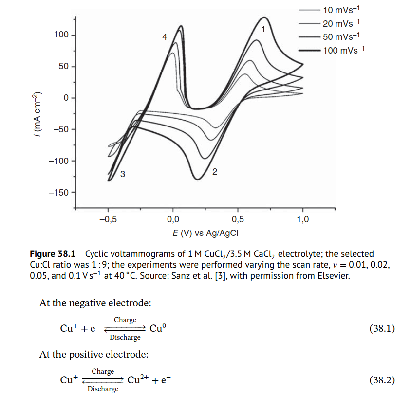
About the copper, oxygen in it would ruin the electrolyte because it would oxidize Cu+ to Cu+2 and this reaction would also increase the pH of the anolyte. This would eventually cause Cu hydroxide to fall out and kill the device. To recover the cell you would need to purge the electrolyte with Argon, cycle the solution over Cu metal to reduce the oxidized Cu2+ back to Cu+ and add hydrochloric acid to adjust the pH back to the proper level if necessary. To run a cell like this you need to make the system quite airtight and ensure the electrolyte is purged with Argon from the start.
An idea to test for a period under oxygen-present conditions is to keep a piece of sacrificial copper in the anolyte reservoir to make sure that any Cu2+ that is formed is reduced back, so that way you would only succumb to the slow pH up creep. However this means that the CE you measure isn't really fair, because you are not accounting for a huge chunk of active material present there. It can be useful however to cycle and perhaps get some insights into other sections of the system under a regular atmosphere. However I don't honestly know if this is good enough, as the reaction of Cu+ with oxygen is quite fast.
The copper chloride (I) initial electrolyte is usually prepared like this (under copper metal) to make sure there is no Cu2+ present when first loading the electrolyte into the device.


