Alternative Electrolytes
-
thanks for this info! FYI I forked your post into a separate topic into the "Electrolyte Development" category just to keep the intro thread relevant.
I am a big fan of Savinell's and Wainright's work at Case! Savinell was on on the all-iron RFB development quite a long time ago... this is one of my highlights from one of his papers in 1981 (!):
Source:
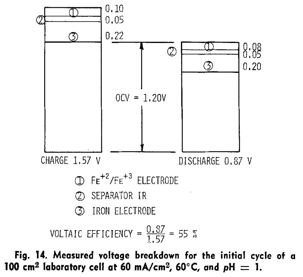
Hruska, L.W. and Savinell, R.F. (1981). Investigation of Factors Affecting Performance of the Iron‐Redox Battery. Journal of The Electrochemical Society. https://doi.org/10.1149/1.2127366.Showing quite clearly the issue of iron kinetics, even at 60 C...
@muntasirms said in Alternative Electrolytes:
In flow batteries, any time you have plating you end up re-tying power density and energy density through that half cell.
Yes, unfortunately, would love to have an all-liquid configuration that plays well with porous separators but asides from iron-chromium (which also has its own set of cons, like HER/high purity req's) there isn't much out there that's easy to start with, which is why we're starting with zinc to get things going.
@muntasirms said in Alternative Electrolytes:
They attempted to scale but really struggled with having a performant enough slurry electrode that wasn't too viscous.
I saw this, I think I skimmed their ARPA-E report (https://www.osti.gov/biblio/1506426) and they also had issues with the cell plugging. IIRC they also licensed the tech to an Australian company?
@muntasirms said in Alternative Electrolytes:
Have you guys looked into water-in-salt electrolytes? They involve dissolving a ton of a supporting electrolyte to the point where they lower the activity of water and suppress HER. I've seen some work using acetate salts and this one using magnesium chloride to support even iron plating - and I've replicated it successfully. The study plates on copper like I mentioned earlier, but I also got it to plate on grafoil.
I am a big fan of this type of electrolyte engineering! The viscosity can also become an issue with this sort of approach too, no? (You are from now the FBRC viscosity expert
 ) I see in that paper though they only cycle up to 0.5 M [Fe], which is quite low in terms of energy density (~8 Wh/L if I'm not mistaken). But it seems solid enough to at least test in the development kit as an exercise. Also a huge confidence boost that you were able to reproduce it and make it plate on grafoil!
@muntasirms said in Alternative Electrolytes:
I did a little study collecting the centralization/governance of various metals and ranked aqueous battery chemistries by cost and "criticality".
Definitely of interest, would love to see it if you're able to share - it's one of my concerns with iodine chemistries at scale (avoiding artisanal iodine production from seaweed).
-
@kirk So my thesis is specifically on slurry/suspension electrodes (instead of using a graphite felt/porous electrode, you suspend conductive carbons with the electrolyte - which also allow you to run solid-phase chemistries in flow) in a way that's sort of chemistry-agnostic. Basically applying chemical reactor design principles to designing slurry electrodes. But here are some salient idiosyncrasies of all-iron cells:
- iron plating in porous electrodes is annoying (acidic = HER, basic = whole host of nasty iron oxides, many of which are quite stable. Plating on carbon substrates is also a pain - most studies I've seen plate onto copper. Also volume expansion is a big pain in static cells. In flow batteries, any time you have plating you end up re-tying power density and energy density through that half cell. Iron plating kinetics are also quite slow, especially in relation to zinc plating.
- Bunch of folks (Savinell and Wainright groups) at case western used slurry electrodes and plated iron onto the slurry particles (ostensibly). They attempted to scale but really struggled with having a performant enough slurry electrode that wasn't too viscous. But plating on suspended particles re-de-couples power and energy density.
- Have you guys looked into water-in-salt electrolytes? They involve dissolving a ton of a supporting electrolyte to the point where they lower the activity of water and suppress HER. I've seen some work using acetate salts and this one using magnesium chloride to support even iron plating - and I've replicated it successfully. The study plates on copper like I mentioned earlier, but I also got it to plate on grafoil.
Solving that performance/viscosity tradeoff in slurry electrodes is part of my thesis! And so is improving the power density of otherwise crappy flow battery chemistries. I'm still working on getting some of it out, but I'd love to share soon or help in any other way.
Material choice from the perspective of mineral centralization and cost is another problem I think regularly about - I did a little study collecting the centralization/governance of various metals and ranked aqueous battery chemistries by cost and "criticality". If that's of interest let me know too!
@muntasirms Thanks for sharing. This is all very interesting. I have made several experiments with Zn/Fe fully symmetric cells (since Zn plates preferably over Fe), using glycine as a chelating agent to make sure Fe stays soluble at mildly acidic pH on the catholyte side. It hasn't really worked very well, I see big increases in ohmic resistance as a function of time, but I don't see any iron oxides forming on the cathode or on the membrane. I don't see full dissolution of the plated metal though, so I bet it has something to do with the oxidation of that metallic deposit (since probably some Fe+Zn alloy is depositing anyway).
I have never tried WISE electrolytes in flow batteries, and had actually never read the Fe+MgCl2 paper you mentioned. I just ordered MgCl2 and CaCl2, so I'll give that a try as soon as I have those salts! If we can get 1M FeCl2 work with MgCl2, then that would be amazing as a demonstration for the kit at both small and large scales.
-
thanks for this info! FYI I forked your post into a separate topic into the "Electrolyte Development" category just to keep the intro thread relevant.
I am a big fan of Savinell's and Wainright's work at Case! Savinell was on on the all-iron RFB development quite a long time ago... this is one of my highlights from one of his papers in 1981 (!):
Source:
Hruska, L.W. and Savinell, R.F. (1981). Investigation of Factors Affecting Performance of the Iron‐Redox Battery. Journal of The Electrochemical Society. https://doi.org/10.1149/1.2127366.Showing quite clearly the issue of iron kinetics, even at 60 C...
@muntasirms said in Alternative Electrolytes:
In flow batteries, any time you have plating you end up re-tying power density and energy density through that half cell.
Yes, unfortunately, would love to have an all-liquid configuration that plays well with porous separators but asides from iron-chromium (which also has its own set of cons, like HER/high purity req's) there isn't much out there that's easy to start with, which is why we're starting with zinc to get things going.
@muntasirms said in Alternative Electrolytes:
They attempted to scale but really struggled with having a performant enough slurry electrode that wasn't too viscous.
I saw this, I think I skimmed their ARPA-E report (https://www.osti.gov/biblio/1506426) and they also had issues with the cell plugging. IIRC they also licensed the tech to an Australian company?
@muntasirms said in Alternative Electrolytes:
Have you guys looked into water-in-salt electrolytes? They involve dissolving a ton of a supporting electrolyte to the point where they lower the activity of water and suppress HER. I've seen some work using acetate salts and this one using magnesium chloride to support even iron plating - and I've replicated it successfully. The study plates on copper like I mentioned earlier, but I also got it to plate on grafoil.
I am a big fan of this type of electrolyte engineering! The viscosity can also become an issue with this sort of approach too, no? (You are from now the FBRC viscosity expert
) I see in that paper though they only cycle up to 0.5 M [Fe], which is quite low in terms of energy density (~8 Wh/L if I'm not mistaken). But it seems solid enough to at least test in the development kit as an exercise. Also a huge confidence boost that you were able to reproduce it and make it plate on grafoil!@muntasirms said in Alternative Electrolytes:
I did a little study collecting the centralization/governance of various metals and ranked aqueous battery chemistries by cost and "criticality".
Definitely of interest, would love to see it if you're able to share - it's one of my concerns with iodine chemistries at scale (avoiding artisanal iodine production from seaweed).
@kirk said in Alternative Electrolytes:
I am a big fan of this type of electrolyte engineering! The viscosity can also become an issue with this sort of approach too, no? (You are from now the FBRC viscosity expert ) I see in that paper though they only cycle up to 0.5 M [Fe], which is quite low in terms of energy density (~8 Wh/L if I'm not mistaken). But it seems solid enough to at least test in the development kit as an exercise. Also a huge confidence boost that you were able to reproduce it and make it plate on grafoil!
Haha I certainly don't feel like much of an expert. Viscosity does become an issue, especially with WISE electrolytes. Actually @danielfp248 if you end up trying out the MgCl2 work, you'll notice that the electrolyte is almost oily. The slurries Savinell and Wainright were working with are even more viscous - something like mayo. I don't remember the exact numbers but I'm happy to point you to more papers if you're interested!
@danielfp248 said in Alternative Electrolytes:
I see big increases in ohmic resistance as a function of time, but I don't see any iron oxides forming on the cathode or on the membrane. I don't see full dissolution of the plated metal though, so I bet it has something to do with the oxidation of that metallic deposit (since probably some Fe+Zn alloy is depositing anyway).
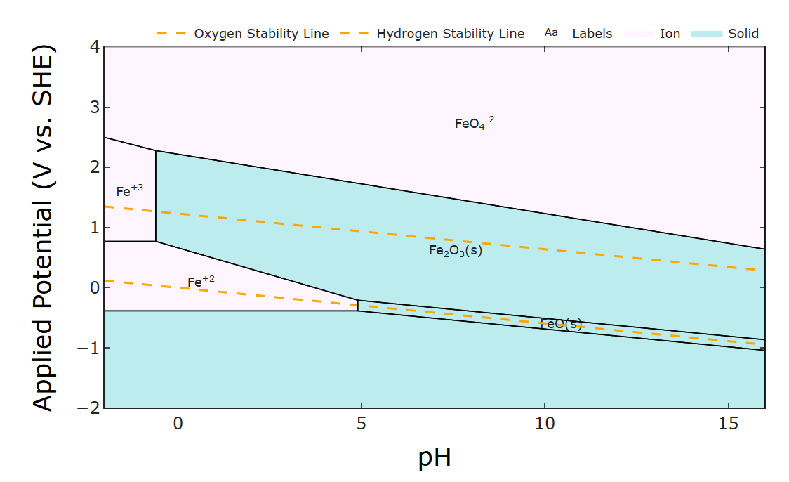
Luckily the oxides don't tend to form in acidic conditions (see the Pourbaix diagram - the phase diagram of stable iron species under varying pH and potential). But HER is more prevalent under acidic conditions. I'm interested in the Zn/Fe half cells though - do you notice any galvanic corrosion/passive loss after you charge the cells? Pourbaix diagrams are an excellent tool for designing thermodynamically possible redox couples. Which leads me to...
@kirk said in Alternative Electrolytes:
would love to see it if you're able to share - it's one of my concerns with iodine chemistries at scale (avoiding artisanal iodine production from seaweed).
I'll let you know when I actually churn out the draft! Might be a bit, but in a nutshell, the low cost (redox active materials under ~$3/kWh) and low criticality (generally abundant and decentralized) aren't too surprising: mostly cells using Fe/Mn/Zn and/or air redox couples meet these criteria. Exact redox couples + electrolyte conditions vary but are based on Pourbaix diagrams.
-
@kirk said in Alternative Electrolytes:
I am a big fan of this type of electrolyte engineering! The viscosity can also become an issue with this sort of approach too, no? (You are from now the FBRC viscosity expert ) I see in that paper though they only cycle up to 0.5 M [Fe], which is quite low in terms of energy density (~8 Wh/L if I'm not mistaken). But it seems solid enough to at least test in the development kit as an exercise. Also a huge confidence boost that you were able to reproduce it and make it plate on grafoil!
Haha I certainly don't feel like much of an expert. Viscosity does become an issue, especially with WISE electrolytes. Actually @danielfp248 if you end up trying out the MgCl2 work, you'll notice that the electrolyte is almost oily. The slurries Savinell and Wainright were working with are even more viscous - something like mayo. I don't remember the exact numbers but I'm happy to point you to more papers if you're interested!
@danielfp248 said in Alternative Electrolytes:
I see big increases in ohmic resistance as a function of time, but I don't see any iron oxides forming on the cathode or on the membrane. I don't see full dissolution of the plated metal though, so I bet it has something to do with the oxidation of that metallic deposit (since probably some Fe+Zn alloy is depositing anyway).
Luckily the oxides don't tend to form in acidic conditions (see the Pourbaix diagram - the phase diagram of stable iron species under varying pH and potential). But HER is more prevalent under acidic conditions. I'm interested in the Zn/Fe half cells though - do you notice any galvanic corrosion/passive loss after you charge the cells? Pourbaix diagrams are an excellent tool for designing thermodynamically possible redox couples. Which leads me to...
@kirk said in Alternative Electrolytes:
would love to see it if you're able to share - it's one of my concerns with iodine chemistries at scale (avoiding artisanal iodine production from seaweed).
I'll let you know when I actually churn out the draft! Might be a bit, but in a nutshell, the low cost (redox active materials under ~$3/kWh) and low criticality (generally abundant and decentralized) aren't too surprising: mostly cells using Fe/Mn/Zn and/or air redox couples meet these criteria. Exact redox couples + electrolyte conditions vary but are based on Pourbaix diagrams.
@muntasirms said in Alternative Electrolytes:
Luckily the oxides don't tend to form in acidic conditions (see the Pourbaix diagram - the phase diagram of stable iron species under varying pH and potential). But HER is more prevalent under acidic conditions. I'm interested in the Zn/Fe half cells though - do you notice any galvanic corrosion/passive loss after you charge the cells? Pourbaix diagrams are an excellent tool for designing thermodynamically possible redox couples. Which leads me to...
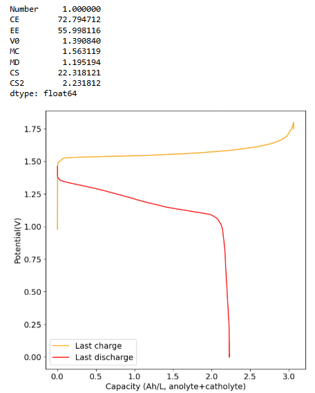
It is puzzling to me because I never saw anything wrong with the battery. I didn't see any obvious corrosion on the anode side, just undissolved metal and on the catholyte I didn't see any Fe oxides forming. You can see a sample of the results below:
This is 2M FeCl2, 3M ZnCl2, 2M Glycine. At 20mA/cm2. Felt on both sides, daramic membrane. The pH of this is 3.2.
As you cycle more the cell degrades quite heavily though (increases in charging potential at the same current and decreases in capacity), no idea why. The pH doesn't increase and I don't see any precipitates on the catholyte, so I have no idea why it dies with time.
-
This is an example of how this decay happens:
-
@muntasirms said in Alternative Electrolytes:
Luckily the oxides don't tend to form in acidic conditions (see the Pourbaix diagram - the phase diagram of stable iron species under varying pH and potential). But HER is more prevalent under acidic conditions. I'm interested in the Zn/Fe half cells though - do you notice any galvanic corrosion/passive loss after you charge the cells? Pourbaix diagrams are an excellent tool for designing thermodynamically possible redox couples. Which leads me to...
It is puzzling to me because I never saw anything wrong with the battery. I didn't see any obvious corrosion on the anode side, just undissolved metal and on the catholyte I didn't see any Fe oxides forming. You can see a sample of the results below:
This is 2M FeCl2, 3M ZnCl2, 2M Glycine. At 20mA/cm2. Felt on both sides, daramic membrane. The pH of this is 3.2.
As you cycle more the cell degrades quite heavily though (increases in charging potential at the same current and decreases in capacity), no idea why. The pH doesn't increase and I don't see any precipitates on the catholyte, so I have no idea why it dies with time.
@danielfp248 said in Alternative Electrolytes:
I didn't see any Fe oxides forming
This aligns with what I'd expect - most iron oxides form at pHs above ~ 5 ish. The most stable ones (magnetite is usually the major problem) form in strongly basic conditions, ph >12 ish.
@danielfp248 said in Alternative Electrolytes:
This is 2M FeCl2, 3M ZnCl2, 2M Glycine. At 20mA/cm2. Felt on both sides, daramic membrane. The pH of this is 3.2.
Hmm...your daramic membrane isn't ion-selective, right? Is it just a size exclusion separator? My first thought is ion crossover (or if you already have both electrolytes mixed, just corrosion). Similar to my question in the Fe-Mn post actually! If your separator isn't ion selective (or you already have all active species mixed together), then any Fe2+ and Fe3+ in electrical contact with Zn metal can drive galvanic corrosion because their reaction voltages differ:
2Fe3+ + Zn <-> 2Fe2+ + Zn2+A couple ways you could ad-hoc test this:
- After charging, let the cell rest but track the open circuit potential over time - if the cell voltage drops fairly quickly (over the course of hours), that could suggest corrosion
- If you want to be more quantitative, you could take a look at mixed potential theory - it predicts what the open circuit potential of a system would be if you have two redox couples that are electrically shorted. Here's a nice preprint from a buddy at @quinnale 's lab that explains it nicely (though fair warning, it's still complicated).
- Try having two separate solutions of the FeCl2+Glycine and ZnCl2+Glycine in each half cell. Unless you have an ion selective membrane, you'll still have ion crossover over time, but it will be slower and your capacity loss shouldn't be as significant.
I think this also explains your lower, but very stable coulombic efficiency.
Granted, if that hypothesis is right, you would've seen this problem from the first cycle. So someone else might have a more accurate view of the problem! Do you guys have the equipment for 3 electrode experiments? That could help with diagnostics. I might make a new post with a list of affordable electrochemical equipment like reference electrodes that I've run into.
-
@danielfp248 said in Alternative Electrolytes:
I didn't see any Fe oxides forming
This aligns with what I'd expect - most iron oxides form at pHs above ~ 5 ish. The most stable ones (magnetite is usually the major problem) form in strongly basic conditions, ph >12 ish.
@danielfp248 said in Alternative Electrolytes:
This is 2M FeCl2, 3M ZnCl2, 2M Glycine. At 20mA/cm2. Felt on both sides, daramic membrane. The pH of this is 3.2.
Hmm...your daramic membrane isn't ion-selective, right? Is it just a size exclusion separator? My first thought is ion crossover (or if you already have both electrolytes mixed, just corrosion). Similar to my question in the Fe-Mn post actually! If your separator isn't ion selective (or you already have all active species mixed together), then any Fe2+ and Fe3+ in electrical contact with Zn metal can drive galvanic corrosion because their reaction voltages differ:
2Fe3+ + Zn <-> 2Fe2+ + Zn2+A couple ways you could ad-hoc test this:
- After charging, let the cell rest but track the open circuit potential over time - if the cell voltage drops fairly quickly (over the course of hours), that could suggest corrosion
- If you want to be more quantitative, you could take a look at mixed potential theory - it predicts what the open circuit potential of a system would be if you have two redox couples that are electrically shorted. Here's a nice preprint from a buddy at @quinnale 's lab that explains it nicely (though fair warning, it's still complicated).
- Try having two separate solutions of the FeCl2+Glycine and ZnCl2+Glycine in each half cell. Unless you have an ion selective membrane, you'll still have ion crossover over time, but it will be slower and your capacity loss shouldn't be as significant.
I think this also explains your lower, but very stable coulombic efficiency.
Granted, if that hypothesis is right, you would've seen this problem from the first cycle. So someone else might have a more accurate view of the problem! Do you guys have the equipment for 3 electrode experiments? That could help with diagnostics. I might make a new post with a list of affordable electrochemical equipment like reference electrodes that I've run into.
@muntasirms Thank for your reply!
To be honest, I am only interested in systems that use microporous membranes (no ion selective membranes) as selective membranes not only drive the initial cost of systems up a lot but can make them very unreliable, as even slight problems with selectivity can lead to solutions going to waste for non-symmetric electrolytes. So, I only study systems where the composition of the discharged anolyte and catholyte is identical and a microporous separator can be used, even if this means sacrificing some CE.
Also note I've seen Fe oxides form at pH values as low as 2.5, there is only a lack of Fe oxide formation because of the Glycine here. Without glycine you do see Fe hydroxide precipitation on the catholyte side on charging as time goes by, even though the measured pH stays below 4.
There is clearly some crossover of Fe3+ and this of course causes some corrosion of the Zn2+, but this should only cause some loss of the CE, it shouldn't lead to increases of ohmic resistance and the cell losing capacity as a function of time. The electrolyte is perfectly symmetrical (both anolyte and catholyte have the exact same composition when discharged), so migration of solution shouldn't be a big problem for short term cycling.
The problem is not that my CE isn't perfect - I obviously expect this from a microporous separator - the problem is that something is happening that is making the capacity go down as a function of time. I have no idea what this should be, but corrosion shouldn't do this, it should just lower the CE (let me know if I'm wrong here).
Also I have equipment to do CVs, but our flow battery does not have the ability to do three electrode experiments atm.
-
@muntasirms Thank for your reply!
To be honest, I am only interested in systems that use microporous membranes (no ion selective membranes) as selective membranes not only drive the initial cost of systems up a lot but can make them very unreliable, as even slight problems with selectivity can lead to solutions going to waste for non-symmetric electrolytes. So, I only study systems where the composition of the discharged anolyte and catholyte is identical and a microporous separator can be used, even if this means sacrificing some CE.
Also note I've seen Fe oxides form at pH values as low as 2.5, there is only a lack of Fe oxide formation because of the Glycine here. Without glycine you do see Fe hydroxide precipitation on the catholyte side on charging as time goes by, even though the measured pH stays below 4.
There is clearly some crossover of Fe3+ and this of course causes some corrosion of the Zn2+, but this should only cause some loss of the CE, it shouldn't lead to increases of ohmic resistance and the cell losing capacity as a function of time. The electrolyte is perfectly symmetrical (both anolyte and catholyte have the exact same composition when discharged), so migration of solution shouldn't be a big problem for short term cycling.
The problem is not that my CE isn't perfect - I obviously expect this from a microporous separator - the problem is that something is happening that is making the capacity go down as a function of time. I have no idea what this should be, but corrosion shouldn't do this, it should just lower the CE (let me know if I'm wrong here).
Also I have equipment to do CVs, but our flow battery does not have the ability to do three electrode experiments atm.
@danielfp248 said in Alternative Electrolytes:
To be honest, I am only interested in systems that use microporous membranes (no ion selective membranes) as selective membranes not only drive the initial cost of systems up a lot but can make them very unreliable, as even slight problems with selectivity can lead to solutions going to waste for non-symmetric electrolytes.
Me too, and that's the route I chose as well (trying to avoid chemistries that required them). Just wanted to ask in case you found an easy/inexpensive solution!
@danielfp248 said in Alternative Electrolytes:
Also note I've seen Fe oxides form at pH values as low as 2.5
Right, that's not too surprising either. Kinetics/rate of formation is difficult to deconvolute from thermodynamic "possibility to form" as it were. Just to clarify, seeing the oxides = orange particulates in the graphite felt?
Some other ideas:
- Does your anolyte yellow over time? I know we're ruling out crossover but that could be another easy way to check - FeCl3 is a deep yellow vs. FeCl2. I'm assuming you've thought of this but I thought I'd suggest it
- You mentioned seeing a lot of undissolved metal on the anode side. Any possibility of dead metal flaking off the felt? In acidic media I wouldn't expect it but who knows. What does the metal on the graphite felt look like usually? any pics?
Thanks for being so responsive. This is interesting
-
@danielfp248 said in Alternative Electrolytes:
To be honest, I am only interested in systems that use microporous membranes (no ion selective membranes) as selective membranes not only drive the initial cost of systems up a lot but can make them very unreliable, as even slight problems with selectivity can lead to solutions going to waste for non-symmetric electrolytes.
Me too, and that's the route I chose as well (trying to avoid chemistries that required them). Just wanted to ask in case you found an easy/inexpensive solution!
@danielfp248 said in Alternative Electrolytes:
Also note I've seen Fe oxides form at pH values as low as 2.5
Right, that's not too surprising either. Kinetics/rate of formation is difficult to deconvolute from thermodynamic "possibility to form" as it were. Just to clarify, seeing the oxides = orange particulates in the graphite felt?
Some other ideas:
- Does your anolyte yellow over time? I know we're ruling out crossover but that could be another easy way to check - FeCl3 is a deep yellow vs. FeCl2. I'm assuming you've thought of this but I thought I'd suggest it
- You mentioned seeing a lot of undissolved metal on the anode side. Any possibility of dead metal flaking off the felt? In acidic media I wouldn't expect it but who knows. What does the metal on the graphite felt look like usually? any pics?
Thanks for being so responsive. This is interesting
@muntasirms Thanks for your reply!
- Does your anolyte yellow over time? I know we're ruling out crossover but that could be another easy way to check - FeCl3 is a deep yellow vs. FeCl2. I'm assuming you've thought of this but I thought I'd suggest it
Chlorides here don't play a strong role as the Gly complexes are much stronger than the chloride ones. The Fe3+Gly complex is extremely red while the Fe2+Gly complex is transparent. There is always some additional Fe3+ - because my starting FeCl2 is slightly oxidized - so the starting electrolyte is already quite red. On charging the anolyte then turns transparent and the catholyte turns completely blood red. They never turn orange. On discharge the anolyte also never turns red, it remains transparent.
- You mentioned seeing a lot of undissolved metal on the anode side. Any possibility of dead metal flaking off the felt? In acidic media I wouldn't expect it but who knows. What does the metal on the graphite felt look like usually? any pics?
No, all the metal remains on the felt. I didn't get any peaks, but the metal looks just like regular plated Zn. It doesn't rust on exposure to oxygen, so it probably contains very little Fe. At Zn/Fe ratios higher than 1.5, Zn seems to plate exclusively, which I confirmed with CV measurements (I see no oxidation peaks for metallic Fe when doing CV, which you do see at lower ratios).
-
For a pointless waste of time search, I tried in google: "what is the best cheapest redox flow battery chemistry"
Came back with:High-energy and low-cost membrane-free chlorine flow battery:
https://www.nature.com/articles/s41467-022-28880-x#:~:text=To meet the needs of,La France in 188428.A high-energy and low-cost polysulfide/iodide redox flow battery:
https://www.sciencedirect.com/science/article/abs/pii/S2211285516304153#:~:text=Highlights * • The polysulfide/iodide redox flow,reversibility of polysulfide and iodide redox chemistries.Air-Breathing Aqueous Sulfur Flow Battery for Ultralow-Cost Long-Duration Electrical Storage:
https://www.sciencedirect.com/science/article/pii/S2542435117300326And 2 Google search options with a lot of results over my head:
Sulfur-Air Hybrid Redox Flow Batteries: https://www.google.com/search?num=10&cs=1&sca_esv=db6c98fd308e1745&q=Sulfur-Air+Hybrid+Redox+Flow+Batteries&sa=X&ved=2ahUKEwjS8bKDhoGPAxXpL0QIHXvhGwgQxccNegQIEhAB&mstk=AUtExfDy0ZazObNsltp9BYwtpQylX9u5AJT5yaQVQRbdARMJvJuEzcAf-Z2d4utwzTSnhCKcn4qOInT9b9zVkToTFJswogvnK4pun2X3x25KeDNW8dbrTS5jwMmIp6riqcFc6wG0Rm8FPMwC2B67TUxmok7FRMfFyfzTWq_Ub_BP2zY5rP4&csui=3Google sure like long URL's
-
@muntasirms Thanks for your reply!
- Does your anolyte yellow over time? I know we're ruling out crossover but that could be another easy way to check - FeCl3 is a deep yellow vs. FeCl2. I'm assuming you've thought of this but I thought I'd suggest it
Chlorides here don't play a strong role as the Gly complexes are much stronger than the chloride ones. The Fe3+Gly complex is extremely red while the Fe2+Gly complex is transparent. There is always some additional Fe3+ - because my starting FeCl2 is slightly oxidized - so the starting electrolyte is already quite red. On charging the anolyte then turns transparent and the catholyte turns completely blood red. They never turn orange. On discharge the anolyte also never turns red, it remains transparent.
- You mentioned seeing a lot of undissolved metal on the anode side. Any possibility of dead metal flaking off the felt? In acidic media I wouldn't expect it but who knows. What does the metal on the graphite felt look like usually? any pics?
No, all the metal remains on the felt. I didn't get any peaks, but the metal looks just like regular plated Zn. It doesn't rust on exposure to oxygen, so it probably contains very little Fe. At Zn/Fe ratios higher than 1.5, Zn seems to plate exclusively, which I confirmed with CV measurements (I see no oxidation peaks for metallic Fe when doing CV, which you do see at lower ratios).
@danielfp248 said in Alternative Electrolytes:
he Fe3+Gly complex is extremely red while the Fe2+Gly complex is transparent
Got it - I actually didn't know that about Fe-glycine complexes. Thank you for teaching me something new today. Could lend to some cool/inexpensive colorimetric characterization.
The plating makes sense given that Zn plating tends to be much faster than Fe plating. The main other thing I could think of is some invisible amount of oxide depositing over time and fouling the surface (may especially be difficult to see in the felt) since at high Fe2+ concentrations oxides will form (at least thermodynamically) according to its Pourbaix diagram (below). Of course kinetics of that deposition is all affected by complexing with glycine and the like so I'm not certain. Intuitively I would say it could be alleviated by decreasing the pH. I wish I could help more but thank you for being so responsive and detailed. Good luck!
-
For a pointless waste of time search, I tried in google: "what is the best cheapest redox flow battery chemistry"
Came back with:High-energy and low-cost membrane-free chlorine flow battery:
https://www.nature.com/articles/s41467-022-28880-x#:~:text=To meet the needs of,La France in 188428.A high-energy and low-cost polysulfide/iodide redox flow battery:
https://www.sciencedirect.com/science/article/abs/pii/S2211285516304153#:~:text=Highlights * • The polysulfide/iodide redox flow,reversibility of polysulfide and iodide redox chemistries.Air-Breathing Aqueous Sulfur Flow Battery for Ultralow-Cost Long-Duration Electrical Storage:
https://www.sciencedirect.com/science/article/pii/S2542435117300326And 2 Google search options with a lot of results over my head:
Sulfur-Air Hybrid Redox Flow Batteries: https://www.google.com/search?num=10&cs=1&sca_esv=db6c98fd308e1745&q=Sulfur-Air+Hybrid+Redox+Flow+Batteries&sa=X&ved=2ahUKEwjS8bKDhoGPAxXpL0QIHXvhGwgQxccNegQIEhAB&mstk=AUtExfDy0ZazObNsltp9BYwtpQylX9u5AJT5yaQVQRbdARMJvJuEzcAf-Z2d4utwzTSnhCKcn4qOInT9b9zVkToTFJswogvnK4pun2X3x25KeDNW8dbrTS5jwMmIp6riqcFc6wG0Rm8FPMwC2B67TUxmok7FRMfFyfzTWq_Ub_BP2zY5rP4&csui=3Google sure like long URL's
@Vorg One issue you will find is that many researchers will overhype their findings, so a lot of technologies might appear way better than they really are once you take a close look at them, especially when you think about using them at or above the kWh scale. All of the technologies you posted have very interesting characteristics - I've read probably all high impact flow battery papers from the last 20 years - but they all suffer from some strong handicaps that basically prevent their mass adoption. Because researchers at the base level do not usually deal with the problems of the kWh scale, they often neglect to account for these in meaningful ways. Even worse, some researchers realize these problems and write the papers in a way that obscures them (so that the paper "sells" the technology better). Sadly because of this, it requires high technical proficiency in the field to correctly evaluate these candidate technologies.
If you just googled you would believe that we have plenty of technologies that were much better than Vanadium, but reality shows only Vanadium flow batteries at large scale. This is part of why I believe our dev kit is important, to lower the entry bar for flow battery research enables people with other priorities to also research the technology and find and study solutions with the idea of scale up in mind, without the pressure to publish over them.
-
@danielfp248 said in Alternative Electrolytes:
he Fe3+Gly complex is extremely red while the Fe2+Gly complex is transparent
Got it - I actually didn't know that about Fe-glycine complexes. Thank you for teaching me something new today. Could lend to some cool/inexpensive colorimetric characterization.
The plating makes sense given that Zn plating tends to be much faster than Fe plating. The main other thing I could think of is some invisible amount of oxide depositing over time and fouling the surface (may especially be difficult to see in the felt) since at high Fe2+ concentrations oxides will form (at least thermodynamically) according to its Pourbaix diagram (below). Of course kinetics of that deposition is all affected by complexing with glycine and the like so I'm not certain. Intuitively I would say it could be alleviated by decreasing the pH. I wish I could help more but thank you for being so responsive and detailed. Good luck!
@muntasirms Thinking about the MgCl2/CaCl2 electrolytes, I started an experiment with 0.5M Fe, 0.5M Glycine and 5M ZnCl2. The thought is that ZnCl2 can also create water-in-salt electrolytes and furthermore, provide the reducing species for the anolyte in this case. I want to see if this degrades in the same way as the normal case with similar ratios of Fe/Zn. The high Zn will affect the Gly chelate formation though, but it should also make Fe hydroxide/oxide formation harder. I'll let you know how that goes. On preparation the solid is oily, orange and hazy, although it doesn't seem to contain any meaningful amount of precipitates.
-
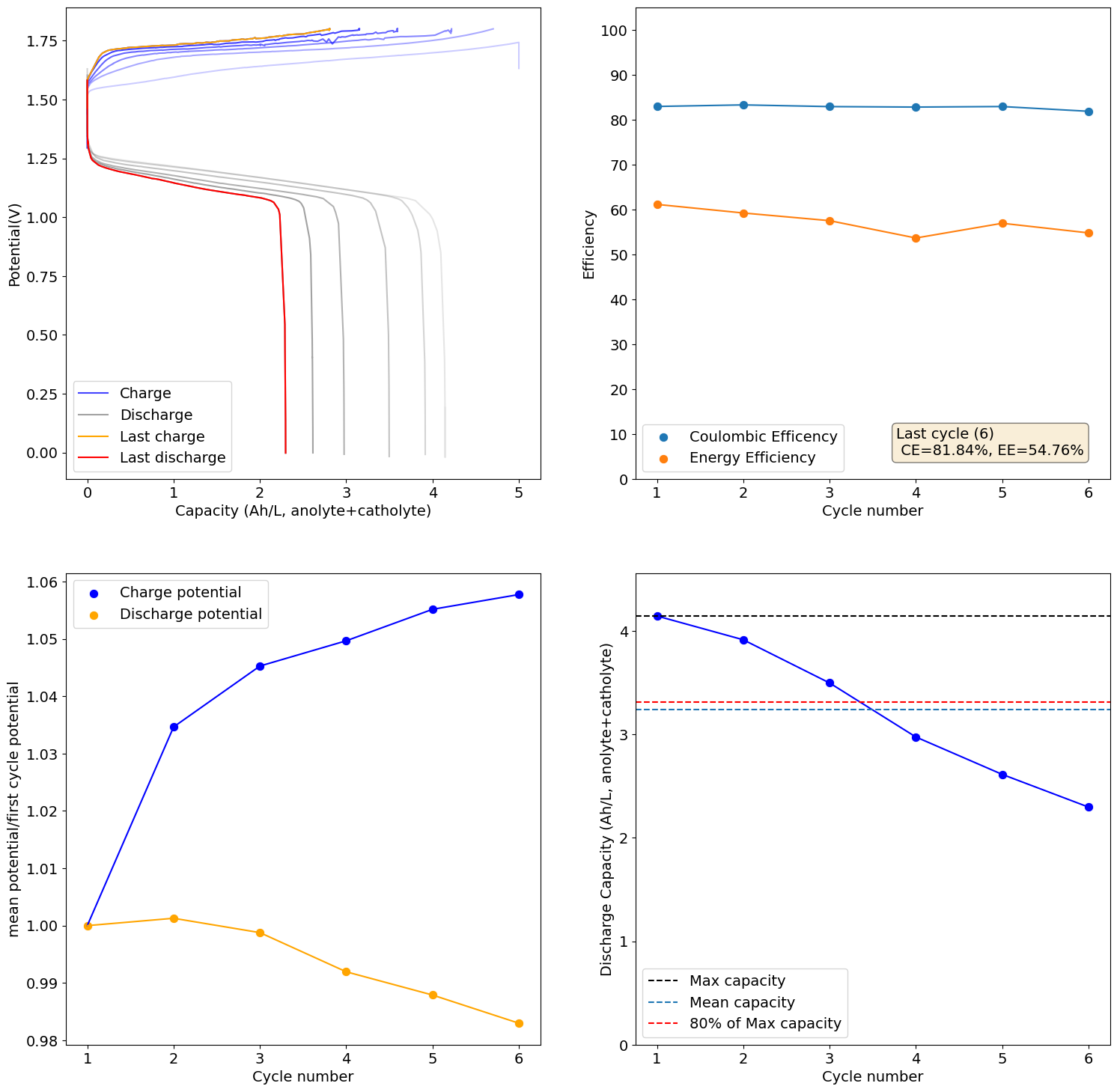
Not surprising that dendrites start to become a problem with Zn concentrations this high. Even at a a capacity of 2 Ah/L I already see a dendrite piercing the microporous layer. Because of the fact that we have reactions of catholyte with the Zn these dendrites are "self-healing" to a degree, but of course charge is lost as these dendrites get consumed.
I am trying to charge to 5Ah/L which would be 75% SOC of a 0.5M symmetric electrolyte.
-
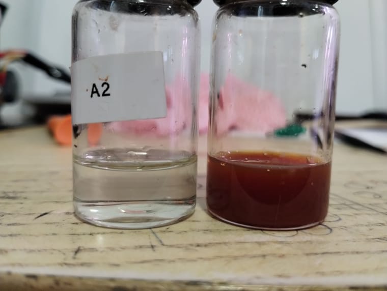
I stopped the charging process and extracted the charged anolyte and catholyte (anolyte left, catholyte right), which you can see below. The catholyte is definitely not clear, but the amount of solid seems small. On addition of 1mL of HCl and mixing the solution becomes clear and yellow (as expected). I will now try cycling this, although I'm afraid it's too acidic for Zn to be stable (although who knows at Zn concentration this high).
-
Once you get it too acidic it really doesn't work anymore. No metal plates at all as the Zn just reacts with the acid to generate H2. Ohmic resistance also increases a lot with cycling.
-
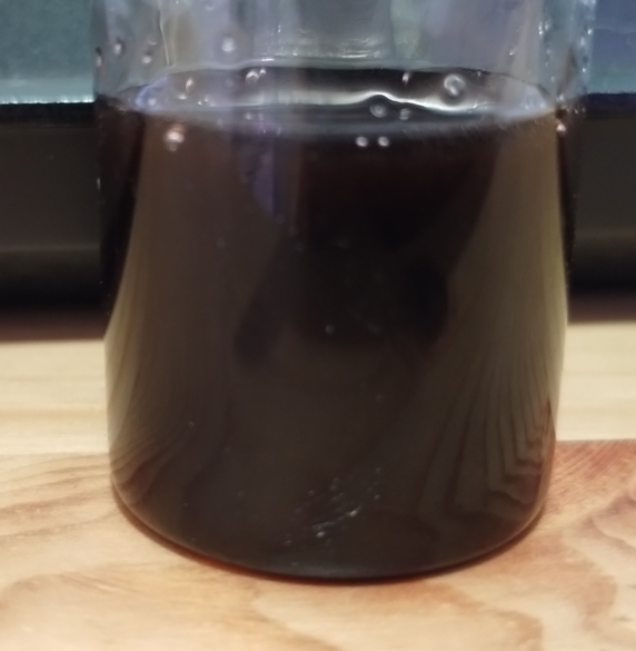
I am now testing 7g ZnCl2, 0.84g FeCl2.2H2O and 0.8g Glycine plus 7mL of water, which gives around 10mL total volume (measured with a syringe). This is around 6M Zn, 0.5M Fe, 1M Glycine. This is how the electrolyte looks on preparation:
I am now testing it with a non-conductive felt on the Zn side, to increase the time it takes for dendrites to form, as they now have to cross the entire cell to reach the membrane. I expect some loss in conductivity but this can be worth the tradeoff. This also increases the time it takes for Fe3+ to react with Zn as it now has to entirely cross the separator and cannot easily meet Zn half way through.
As you can see the solution is not entirely translucid, because there is some slight Fe oxide impurity in the FeCl2 I use.
-
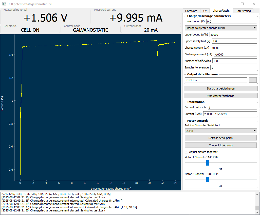
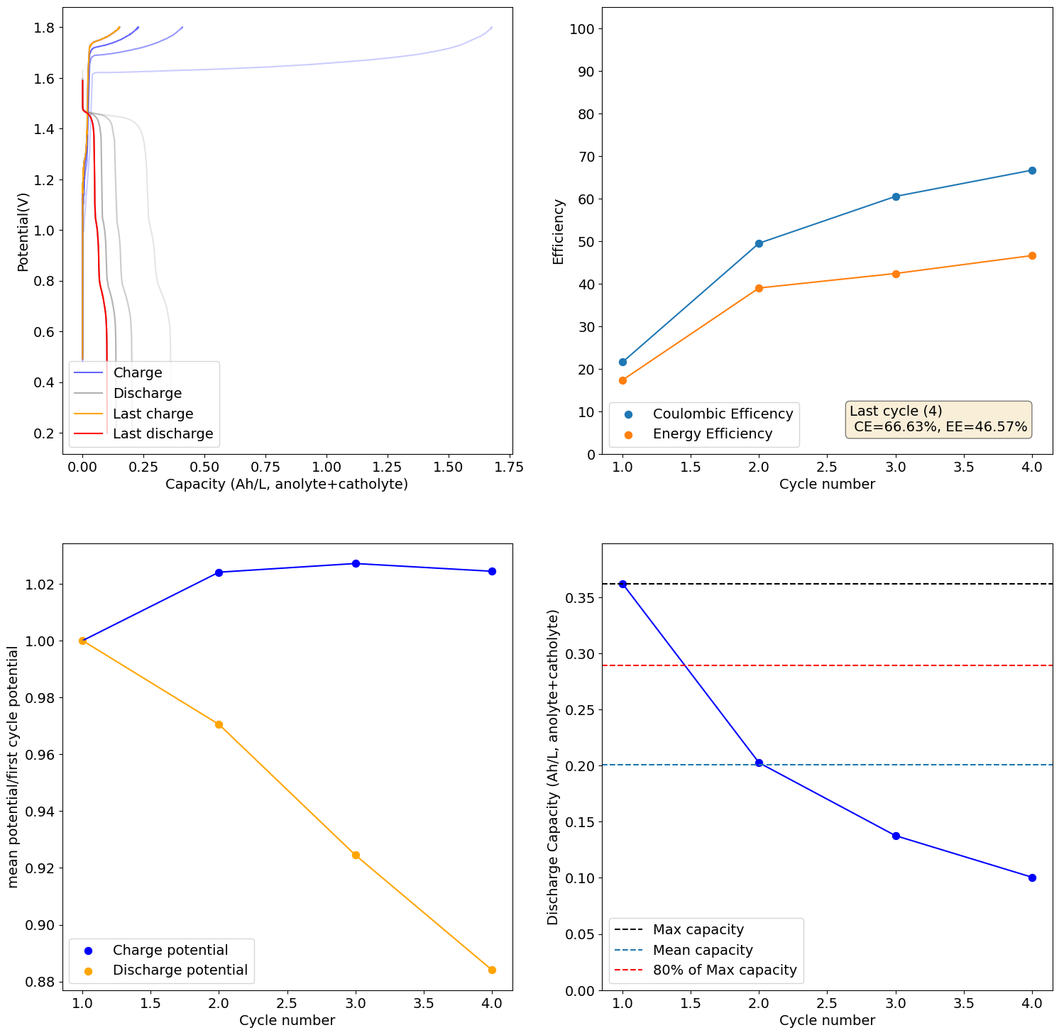
Charging to 2Ah/L (~30% of SOC at 0.5M Fe) shows promising results, although CE and EE are still quite low. I will try charging to 5Ah/L next.
-
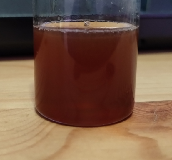
I also prepared a test electrolyte with 6.8g of ZnCl2, 3.2g of FeCl2.2H2O, 2.25g of Glycine with 5.5mL of water to reach a volume of 10mL and concentrations of 5M Zn, 2M Fe and 3M Glycine. The electrolyte is deep red as shown below. The 100% SOC mark for this electrolyte would be ~26Ah/L but I would honestly be more than happy if it cycled to 15Ah/L in a stable manner. I will test this electrolyte once I'm done testing the 0.5M Fe electrolyte I'm running atm.
-
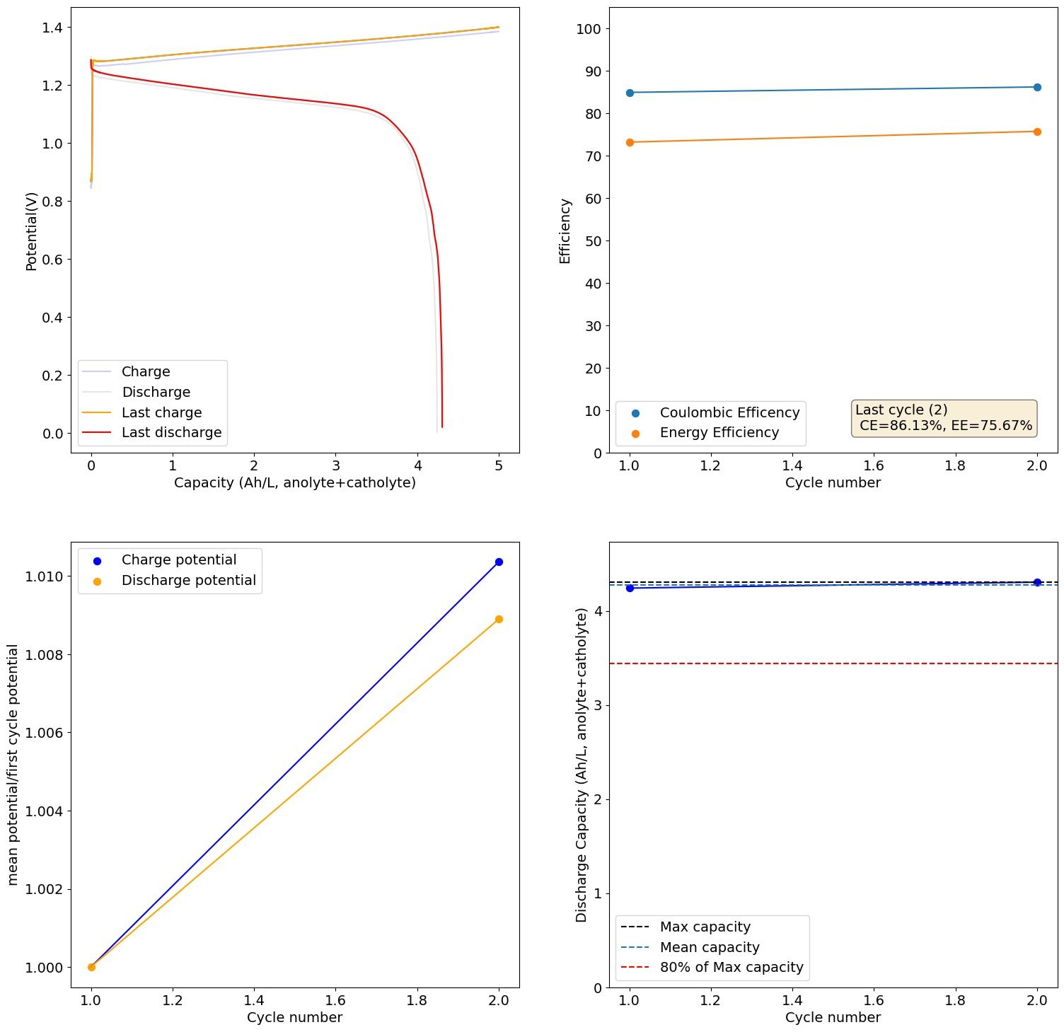
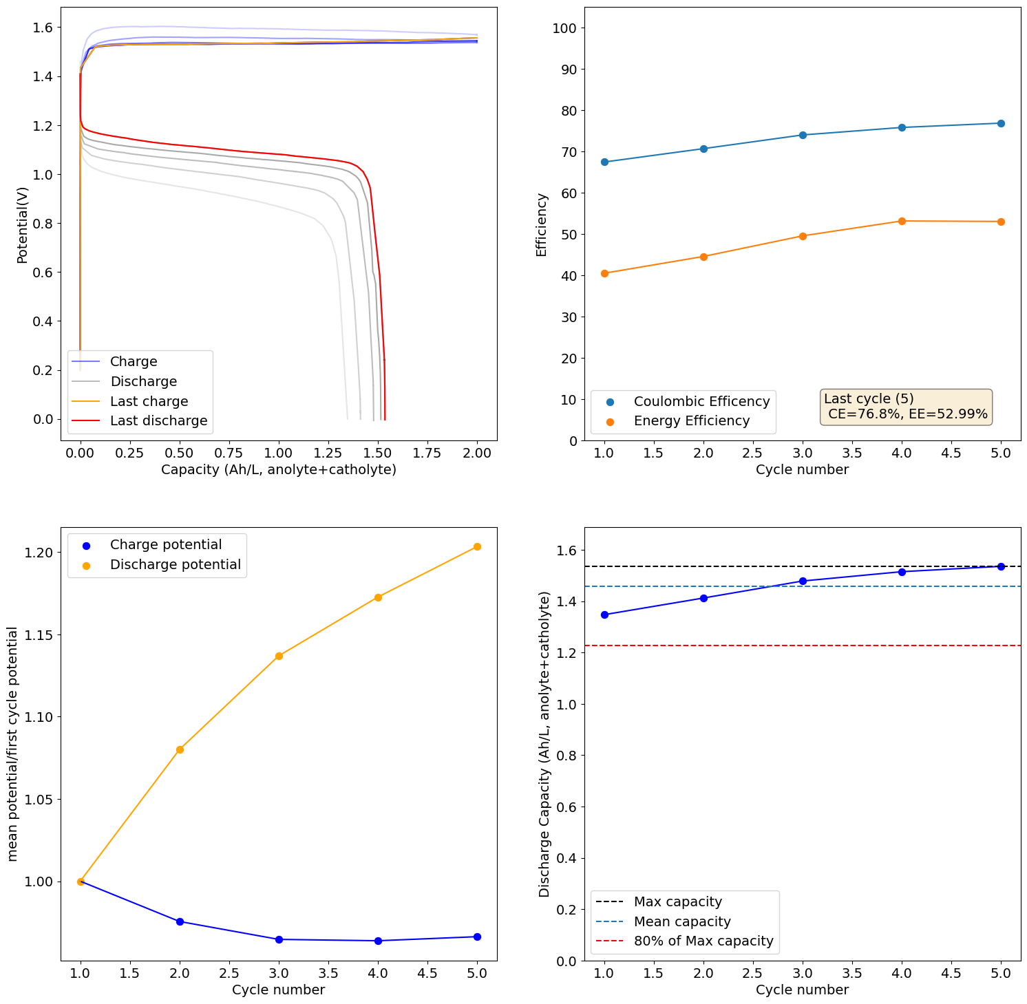
The 0.5M Fe solution at a current density of 5mA/cm2 reached the Nernst limit at around 3.1Ah/L. This is the first cycle:
I will keep you posted on how the cycling goes and if it degrades in capacity as other similar tests have done in the past.
Hello! It looks like you're interested in this conversation, but you don't have an account yet.
Getting fed up of having to scroll through the same posts each visit? When you register for an account, you'll always come back to exactly where you were before, and choose to be notified of new replies (either via email, or push notification). You'll also be able to save bookmarks and upvote posts to show your appreciation to other community members.
With your input, this post could be even better 💗
Register Login