Long term cycling of our Flow Battery kit using a Zn-I chemistry

-
Our goal at the Flow Battery Research Collective (FBRC) during the past year has been to develop and manufacture a flow battery kit that can be used to study flow batteries at a small scale in a low cost yet reproducible manner. Today I want to discuss all the problems we have found when attempting long term cycling in both versions of our kit and how we have addressed them so far.
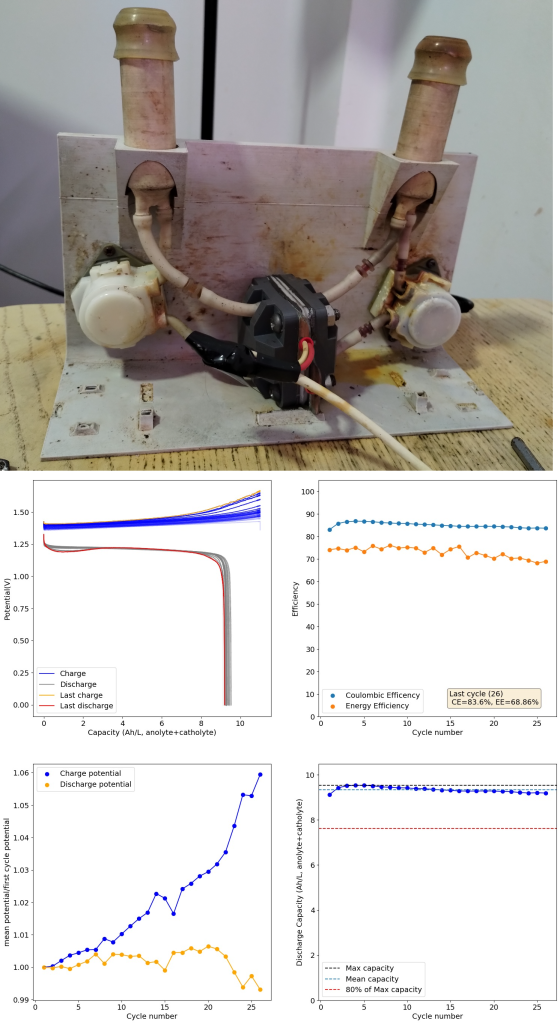
Long term cycling results with the first version of our kit. Around 5 days of cycling. Our first kit design – which you can see above – was able to do long term cycling of an electrolyte composed of Zinc Chloride (1m) and Potassium Iodide (2m) in a potassium acetate/acetic acid buffer (pH=5.2). We were able to obtain capacities higher than 10Ah/L (on total volume of electrolyte — note previous values on this blog were based on catholyte only) without much capacity fade at the 25 cycle range. I didn’t try longer term cycling because of issues with pumps getting damaged by the tubing I was using leaking iodide (see how orange the right pump above looks, that’s not supposed to happen). At this point we were also testing several types of tubing, reason why you can see different colors of tubing in the setup.
However, this design had two big issues. The first is that the polypropylene bodies were getting over compressed at the top and under compressed at the center, so after a single long term cycling event (cell cycling for 5 days), the cell would never seal well again after being opened due to warping of the body. This made this design completely unfeasible and forced us to accelerate the development of v2.
Long term cycling results of second version of our kit. Cycling was also around 5 days. The second cell design – showed in the second image above – has a square design with even compression and complete isolation of the cell body from the electrolyte by using a sealed polypropylene flow frame (you can read more about it in the FBRC website). However, despite using the exact same electrolyte and membrane, this design has been showing some increasing decay of the electrolyte as a function of time. The cycled capacity is a bit lower and after 28 cycles the testing had to be stopped due to obvious deterioration of the charging potential.
Flow batteries using microporous membranes can suffer from significant issues related to hydraulic pressure differences between anolyte and catholyte. As the battery is cycled, there is net water transfer between both sides and this can lead to the accumulation of polyiodide species in a Zn-I flow battery. This deteriorates the charging potential and reduces the SOC of the battery. You can ready more about this decay mechanism in this paper. When my testing was done, there was indeed an almost 50% less fluid in the anolyte vs the catholyte side, interestingly the completely opposite effect when compared to the paper. Changing the supporting electrolyte concentration or Zn salt used – to make the water changes less extreme – or adjusting electrolyte flow rates, can help eliminate these volume balance issues.
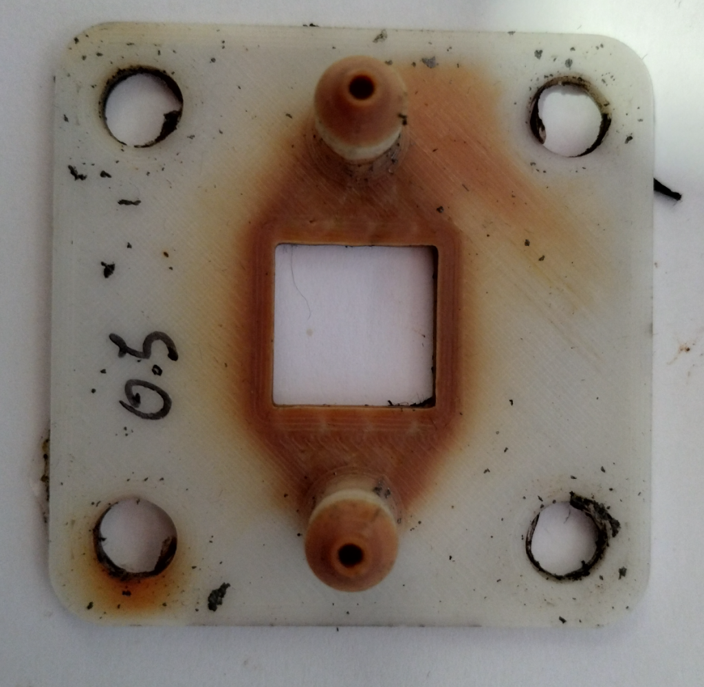
New flow frame design for the second version of our kit. You can see the flow channel has been colored red by the catholyte. The flow frame was 3d printed. Since 3d printing leaves some porosity (even at 100% infill) you can see some coloring even away from the flow channel. There are however other problems with the current tests. The first is that the chemistry is not stable to oxygen – both due to iodide and zinc reactivity – so working under atmospheric conditions without any inert gas purging of the electrolyte has likely made my tests more unstable, due to Zinc passivation and pH instabilities caused by the reactions of iodide with oxygen. Since the new flow frames are 3d printed – therefore not 100% free of pores – they might be letting more oxygen in, which might also be why the system is more unstable than v1 in this regard. Getting flow frames manufactured through polypropylene sintering or injection molding could get rid of this issue.
Another issue – shown below – is the use of graphite foil (grafoil) as our electrode material. Although grafoil does the job fine, it does seem to be porous to iodine, which crosses it and reacts with the underlying copper, increasing series resistance and creating a protuberance on the copper plate (which is readily visible in the image after long term cycling). I scratched the grafoil to then reveal a white powder, which is copper iodide, leading to a further loss of capacity. This problem could be solved by using a proper bipolar plate material or by sealing the grafoil in some manner. Thicker grafoil could also be enough to ameliorate the problem.
Catholyte side graphite foil, 0.5mm, after 5 days of cycling. You can see a bump in the foil caused by buildup of copper iodide material below the electrode. A high capacity short cycle result using a Zn-I electrolyte. This is using total volume of electrolyte, so a capacity that would be in line with current Vanadium batteries. I also want to note that we have achieved much higher capacities – see above – although not in long term cycling, as these higher capacities generate much more concentrated electrolytes that have significant problems (such as the precipitation of insoluble solid elemental iodine and the corrosion of the pumps and copper current collectors).
As you can see, getting long term cycling results is not easy. There are many hurdles to overcome to be able to provide a kit that is able to cycle a chemistry like Zn-I long term, without any problems, in a reproducible manner. All these hurdles can be overcome though – as there are plenty of examples of people cycling these batteries long term – so it is a matter of arriving at a proper combination of materials and chemistry. Our work continues! Thanks a lot for all your support.
This flow battery kit work is being funded by the Financed by Nlnet’s NGI0 Entrust Fund. We are also collaborating with the FAIR Battery project.
-
 K kirk shared this topic on
-
Nice work, Daniel. I am thinking of plumbing solutions to the imbalance issue:
From A review of all-vanadium redox flow battery durability:
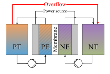
After studying the capacity fade for mixed acid electrolyte, UET [154] found that, during long‐term operation, the ratio of catholyte and anolyte concentration remained constant: 1.3:1. Based on this finding, they designed an overflow system with different volume (volume ratio: 1.3:1) anolyte and catholyte tanks, in which the volume ratio and total vanadium were kept constant. With the new design, the VRFB achieved long term capacity and efficiency stability. However, this design is only valid for the mixed acid electrolyte system. Recently, Wang et al [152] developed an electrolyte reflow method to solve the electrolyte imbalance issue for the sulfuric acidvanadium electrolyte system. Figure 10 shows the schematic of their method; without reflow, eventually all of the anolyte will move to the catholyte tank, while with reflow, the anolyte tank will always contain some electrolyte. Similar to the UET method, the volume ratio of catholyte to anolyte is a key parameter affecting the capacity stability and is highly dependent on the operating current density. Cycle life and total capacity were all improved with the reflow method.
There is also Capacity balancing for vanadium redox flow batteries through electrolyte overflow but it was retracted - they think they accidentally had a pinhole in their membrane for the test. But they did build a real overflow system:
Hello! It looks like you're interested in this conversation, but you don't have an account yet.
Getting fed up of having to scroll through the same posts each visit? When you register for an account, you'll always come back to exactly where you were before, and choose to be notified of new replies (either via email, or push notification). You'll also be able to save bookmarks and upvote posts to show your appreciation to other community members.
With your input, this post could be even better 💗
Register Login