Only Fe system
-
Just wondering, you are using water, but are you using distilled, or de-ionized, or just tap? The reason for the question is, when/if this becomes a doable project for home battery system, our tap water is very hard. It is a mix of ground water which is some what hard and CAP water which is water that has flowed for some 336 miles across the desert in an open canal diverted from the Colorado river making it VERY hard. Seems likely it would throw off the chemistry.
-
I did a cycle to 4Ah/L at 5mA/cm2 (~30% of available SOC at 1M Fe). As you can see below the CE is above 93% (even though it took 7+ hours to do the charge/discharge) and the EE is above 50%. I am now going to charge this to the Nernst potential (cutoff at 1.4V). See what I get at 100% SOC.
-
While the above runs I also prepared a 1M Fe and 4.5M Ca electrolyte using 1.6g of FeCl2.2H2O and 6.6g of CaCl2.2H2O. I did this to perform CV experiments, as a CV was never done on the original paper that discussed the Ca/Mg WiSE electrolytes for Fe plating. The CV experiments were done with a glassy carbon working electrode, a graphite counter electrode and an Ag/AgCl reference electrode.

The stripping efficiency seems really high and the standard potentials come out at -0.68V for the Fe2+/Fe0 and +0.56V for the Fe2+/Fe3+. This means our max potential on the Fe/Ca system should be 1.2V (shouldn't be far for the Fe/Mg) system, which suggests we are suffering from kinetic problems of one of the reactions on the untreated felt. I will test some felt treatments (heat and hypochlorite) to see if these can improve the VE. Fe is known to have kinetics problems on untreated felts, the CV confirms we should be able to get a much higher potential from this chemical system.
-
Plating/stripping experiments in the Fe+Ca electrolyte show that the Fe deposition is >99% reversible. As in the CV there is no evidence of HER at all, there isn't any bubble formation of the working electrode at all, neither is there any degradation of the plating with cycling.

Doing experiments at multiple plating times (5, 10, 30, 60 seconds), plating at -0.9V and stripping at -0.5V (10 plate/strip cycles per experiment), shows the behavior is basically reversible.

-
The Fe/Mg cell died when I tried the higher SOC values. The cycle took a long time (so the CE was a lot lower because of the microporous membrane) but the next cycle showed very ample deterioration of the cell. On opening of the cell there was evidently a lot of undissolved metal on the anode side and a lot of Fe hydroxide had fallen out of solution and basically accumulated inside the reservoir.

I then cut the daramic separator in half and took a 30x image using a microscope.

Clogging of the separator by hydroxide that forms on the metal surface is likely a problem with a setup with carbon felt on both sides.
I have now started a cell with a non-conductive separator on the anode side, to see how results change.
-
So I realized that my mystat potentiostat lost calibration somehow, so all the experiments on this thread were done with a -0.3V bias. This means that in reality I only discharged to 0.3V and all charging and discharging potentials are actually +0.3V higher. The CV and plate/strip experiments don't have this problem as I used another mystat that was properly calibrated.
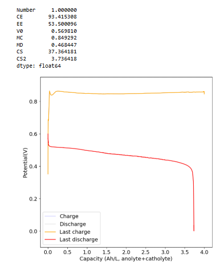
I recalibrated my mystat to ensure it is properly zeroed and got curves that make much more sense. This is for a new electrolyte I prepared with 1M Fe from FeCl2.2H2O, 2.5M CaCl2 and 1M NH4Cl (I added this as ammonium often helps prevent metal passivation). I also added 10mg/mL of citric acid, to serve as a buffering agent.
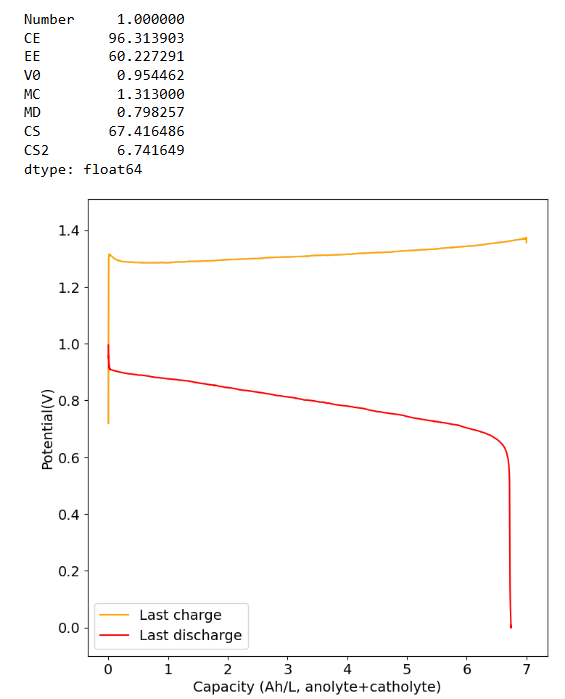
These are curves obtained at 0.5Ah/L charge/discharge at 10mA/cm2:
As you can see the potential has now stabilized and the final CE and EE values are quite good (for all Fe at least!). The discharge potential is also now +0.87V, which is in much better agreement with my CV values.
-
 K kirk@social.coop shared this topic on
 V victor_tokarev@twiukraine.com shared this topic on
-
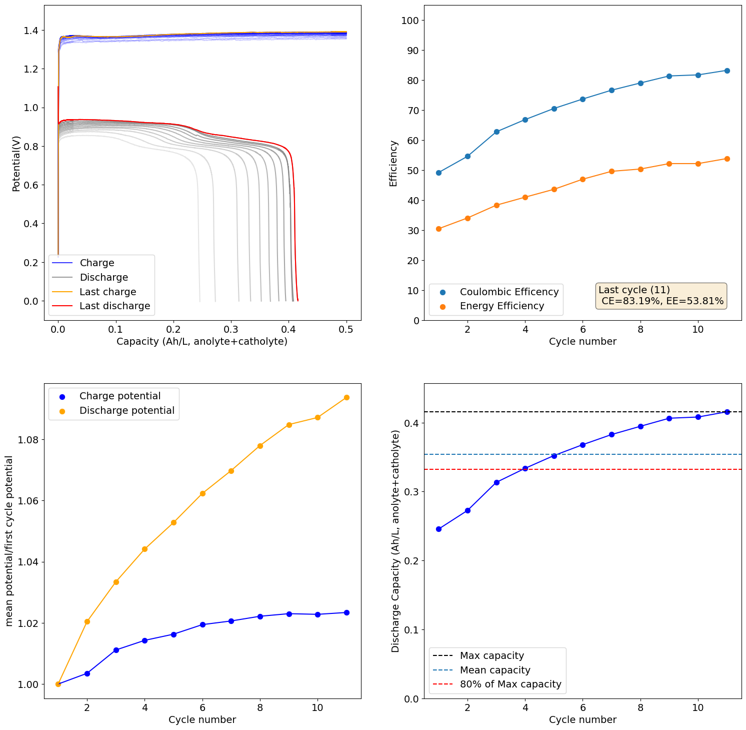
Cycling of the 1M Fe from FeCl2.2H2O, 2.5M CaCl2 and 1M NH4Cl cell to 4Ah/L gave pretty good results, with even some improvements to CE and EE with cycling. I am now doubling the current to 20mA/cm2 and trying to take it to the Nernst limit, see how it does then.

-
Cycling of the 1M Fe from FeCl2.2H2O, 2.5M CaCl2 and 1M NH4Cl cell to 4Ah/L gave pretty good results, with even some improvements to CE and EE with cycling. I am now doubling the current to 20mA/cm2 and trying to take it to the Nernst limit, see how it does then.
@danielfp248 said in Only Fe system:
take it to the Nernst limit
-
This sounds very exciting but to be honest, as an outsider, I can't really judge. Could you explain how this chemistry compares to others and how the results are promising, etc? Also, is the low voltaic efficiency due to overpotentials because of relatively bad kinetics?
-
This sounds very exciting but to be honest, as an outsider, I can't really judge. Could you explain how this chemistry compares to others and how the results are promising, etc? Also, is the low voltaic efficiency due to overpotentials because of relatively bad kinetics?
@sepi Thanks for writing. It is exciting in the sense that Fe systems are great because Fe is low cost, low toxicity, easy to source and very sustainable given how much Fe is present in the earth's crust. However, Fe systems suffer from big problems with hydrogen evolution, as H2 evolution occurs easily at acidic pH (which is needed for the Fe3+ species to be stable in solution). In turn, H2 evolution increases the electrolyte's pH, which then causes problems with Fe hydroxide precipitation. These problems have prevented massive adoption of Fe chemistries in flow batteries, in spite of all the above mentioned advantages.
I had personally never been able to have an Fe system work with our battery system, so the excitement comes from finally having some electrolyte configurations that are sort of working well (at least cycling well at low SOC values with significant CE and EE). The big issue is that there isn't any stability in cycling at high SOC values yet, but at the current state you can run experiments with our kit and help develop Fe battery systems.
The potentials are lower than those expected from the CV experiments, but after recalibrating my potentiostat the losses are actually lower than I thought. So I am now getting potentials near the 0.95V when going to high SOC values.
-
Thanks for the comprehensive reply, that sounds indeed very nice! I have more questions still:
- Do you do anything differently than what is already published or is the challenge mostly to get something kind of proven working in the FBRC devkit?
- Would it in general be an issue to just never charge the battery to high SoCs? Sure your volumetric energy density will go down but you might avoid all kinds of trouble this way. I imagine habing a very simple or lowtech battery of mediocre efficiency and density could still be of a lot of value to many people.
- Are the low voltages due to ohmic losses in the separator and maybe electrolyte?
- How is the patent situation around this technology?
@sepi To answer your questions:
-
We are testing concentrated MgCl2 and CaCl2 electrolytes, which have never been published in all-Fe flow batteries. The experiments are therefore innovating in the space.
-
It wouldn't be an issue and in fact this is how Zn-Br commercial flow batteries work, to make them stable they are never charged beyond something like 20-30% of their SOC. The Zn-Br batteries have high enough capacities at 20-30% SOC to make them still quite dense at this much lower SOC rating. For an all-Fe flow battery this would be so low that the cost per kWh would climb a lot, but of course you can always go this route if the compromises are worth it to you.
-
The max voltage the all-Fe chemistry we're studying could give would be around 1.2V given the CV. Ohmic losses because of the solution conductivity and separator thickness are likely a meaningful component of our drop, so are likely the kinetics of plating/stripping and Fe2+/Fe3+ reactions on carbon felt.
-
As far as I know, the main patents on Fe plating flow batteries were issues in the mid 80s, so most of the original patents of this technology have expired. However there are a lot of patents in Fe batteries, particularly dealing with electrolyte modifications and electrode modifications (to reduce H2 evolution).
-
@sepi, FYI, conventional all-iron RFBs at scale require a system to recombine the produced hydrogen from the negative side with the excess Fe (III) cations ("ferric") on the positive side. This reaction liberates protons to restore the acidity of the system and prevent hydroxide precipitation. This is, technically, a hydrogen-ferric fuel cell. However, it is another tricky system to implement, and can require catalysts (e.g. platinum). A lot of patents deal with this issue. ESS's "proton pump" is effectively this.
-
I also just made a blog post on this chemistry, with some of the latest results https://chemisting.com/2025/09/15/studying-an-all-fe-chemistry-using-wise-in-our-flow-battery-kit/
-
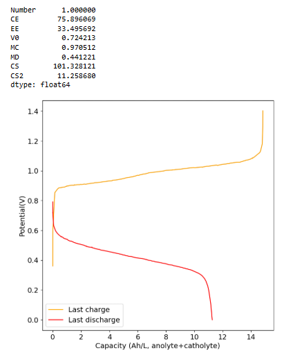
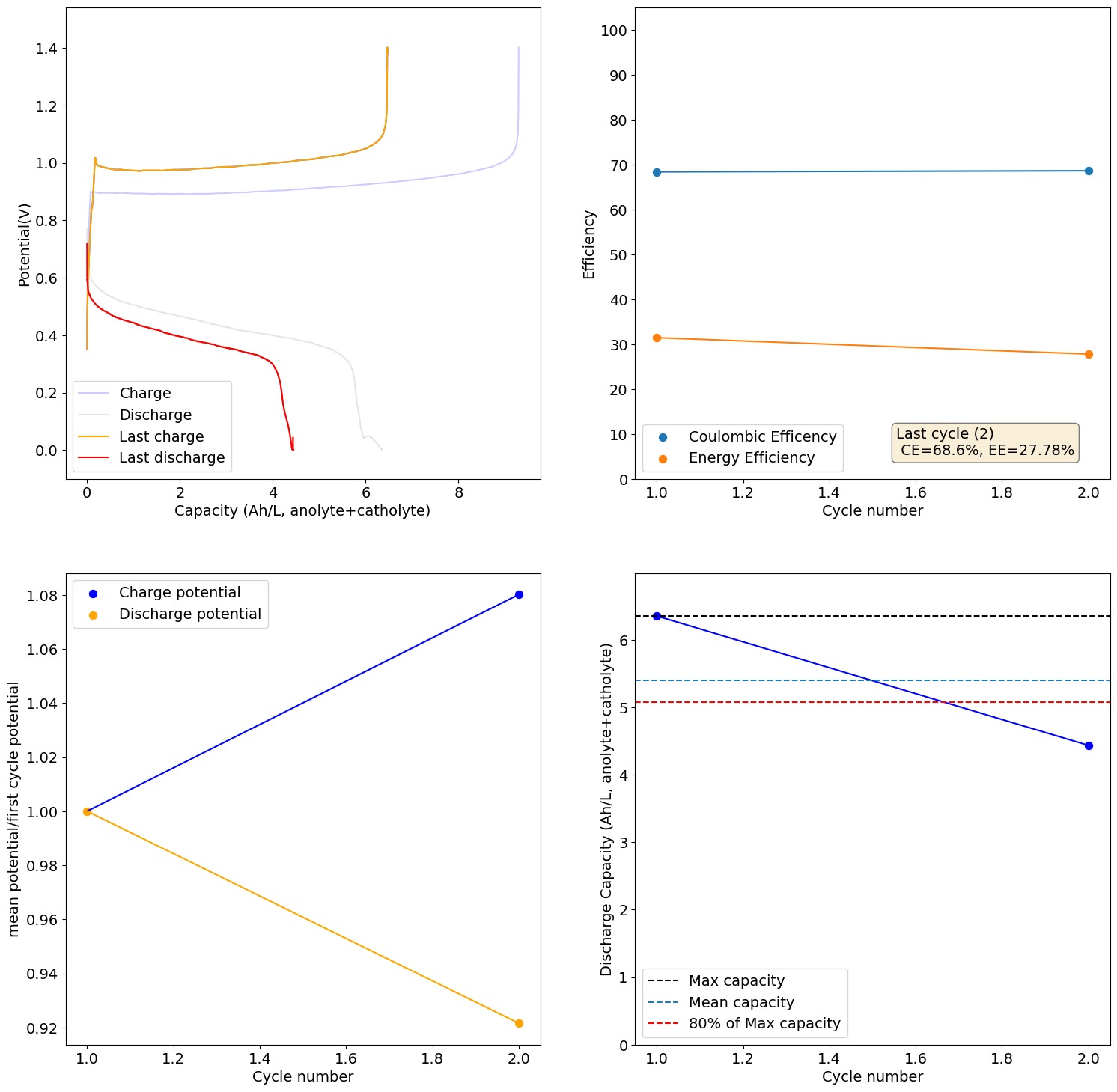
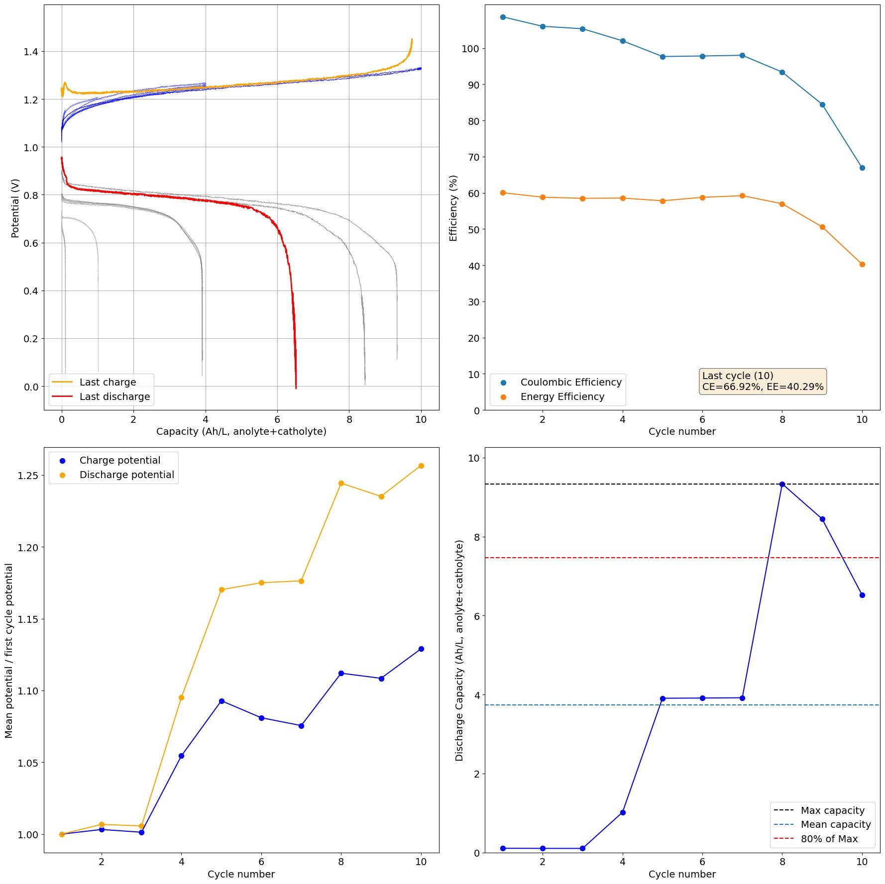
This is the result of charging the 1M Fe, 4.5M CaCl2, 1M NH4Cl cell to the Nernst limit (1.5V)
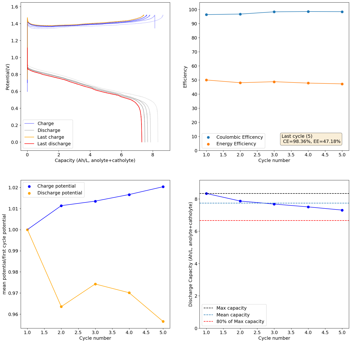
There is still some decay in capacity due to increases in resistance, although much slower. I will now charge this to 6.5Ah/L, see if it can cycle in a stable manner at that capacity.
-
Running to only 7Ah/L at 10mA/cm2 (1M Fe, 4.5M CaCl2, 1M NH4Cl)
-
This test showed some deterioration on cycling:
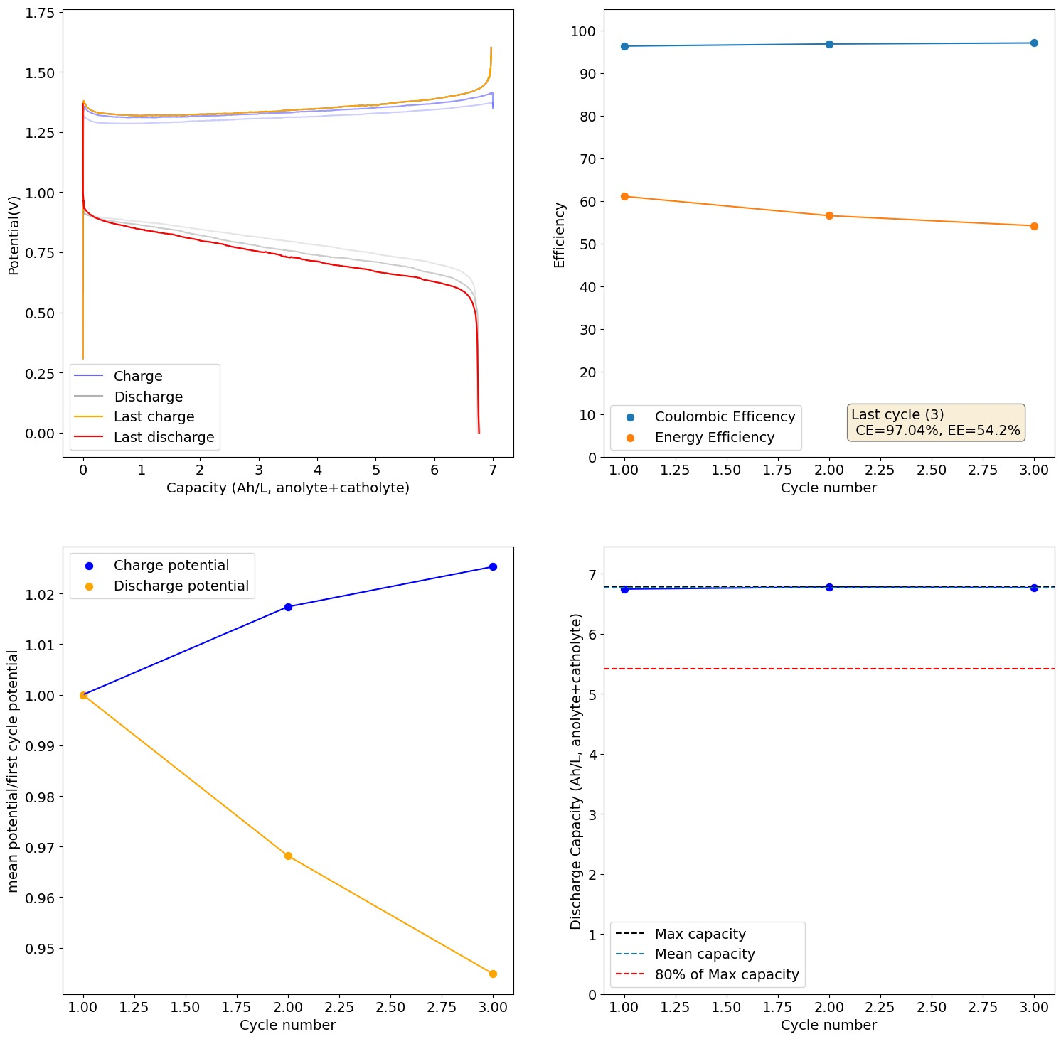
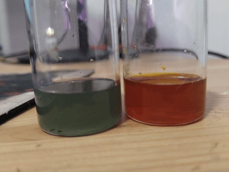
I took out the catholyte and anolyte when charged (you can see the anolyte (left) and catholyte (right) in the pictures below). There isn't any hydroxide precipitation in either one. However there are some pieces of detached Fe metal on the anolyte, which I think are what causes the slight loss in capacity and increases in ohmic resistance as a function of time.
-
 K kirk referenced this topic on
-
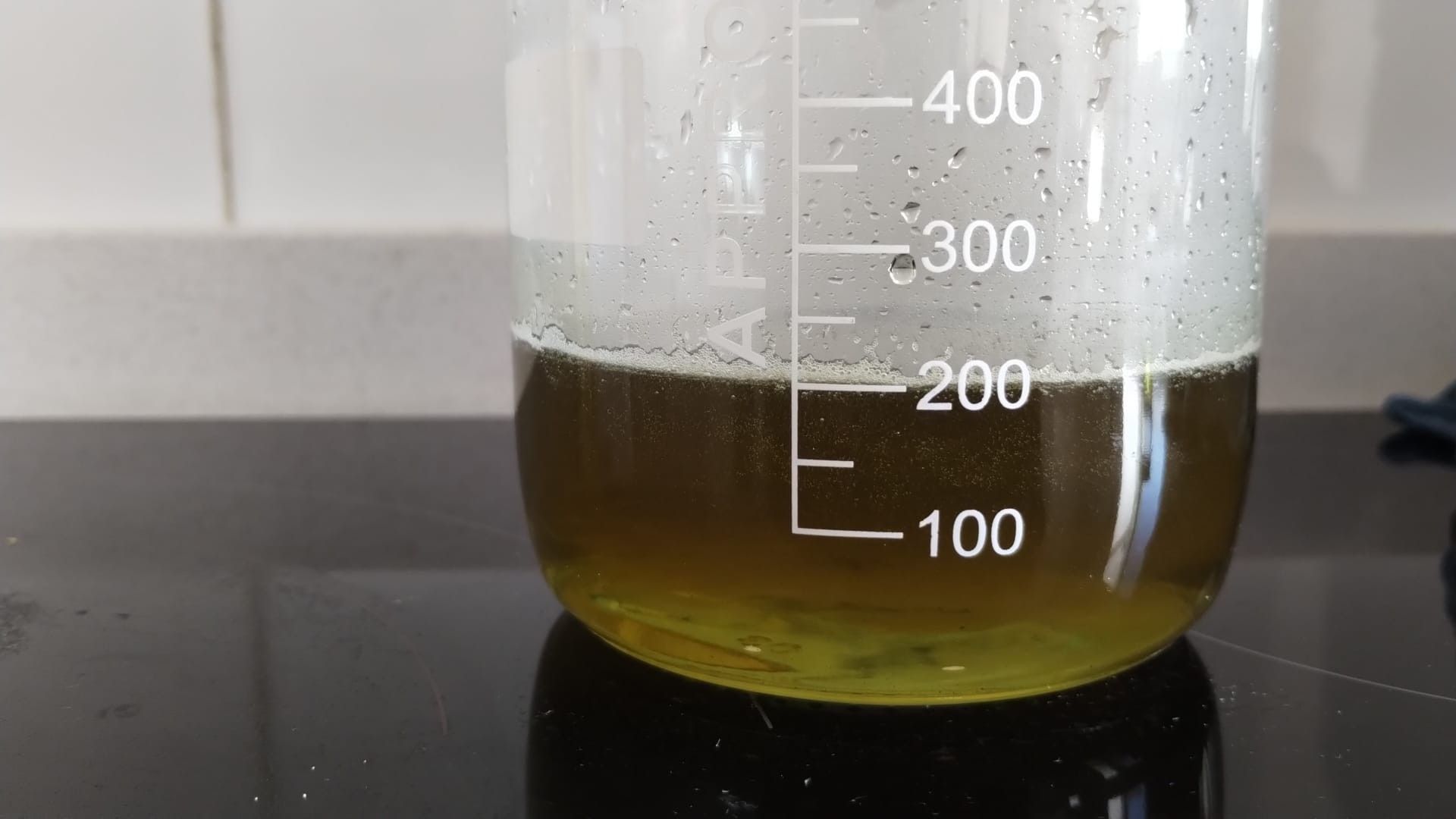
I prepared a bulk amount of solution to have a more standard mix. This is 90g MgCl2, 32g FeCl2.2H2O, 2.5mL 15% HCl, 0.75g of Ascorbic acid. Volume to a total 200mL using a volumetric flask, then transferred to store here.
Initial MgCl2 addition was done in a 1L beaker over around 150mL of reverse osmosis water, added HCl after, then Fe, then ascorbic, then waited to cool, transferred to volumetric flask to finalize vol, then put into storage.
If you prepare this be very careful as MgCl2 reacts very exothermically with water. Cool the water in an ice bath and add slowly.
Final solution is perfectly clear.
The above correspond to molar concentrations of around 0.98M Fe and 4.7M Mg.
The HCl is to ensure complete dissolution of any Fe3+ hydroxyde/oxide contamination and the ascorbic acid is to reduce any present Fe3+ into Fe2+. Excess ascorbic has to react on initial charge, so it will eat into a tiny bit of the SOC.
-
Did a few cycles at low SOC and then attempted to cycle at 10Ah/L.
Catholyte (left) anolyte (right) below:
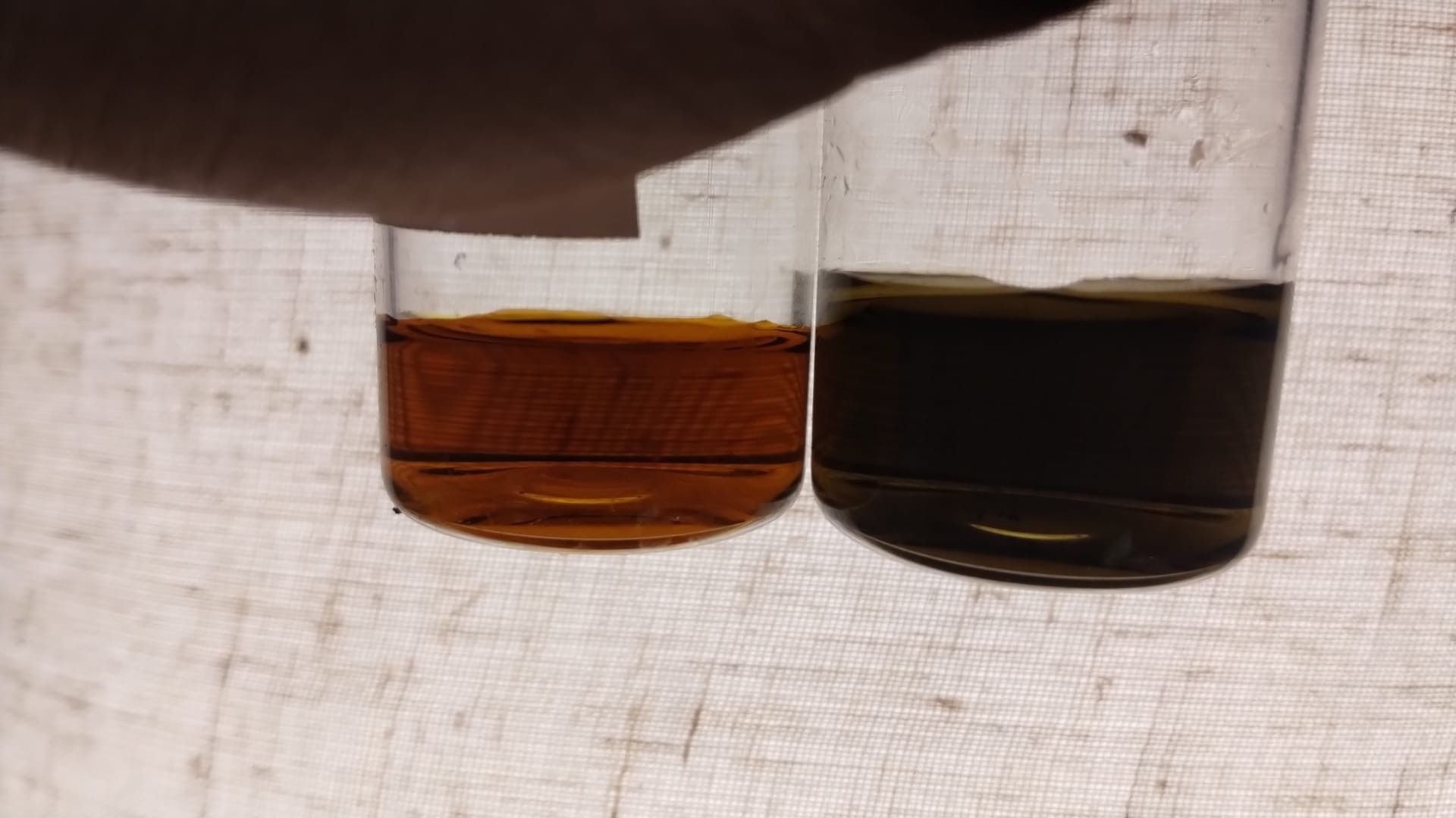
pH of catholyte was 0.24 and anolyte was 4.7. As you can see on second cycle to 10Ah/L the CE dropped from 93% to 83% and then capacity continued to decrease. On disassembly a lot of unreacted passivated iron remained on the anode, likely due to the pH increase. As Fe deposits water activity likely increases, which increases HER, which increases pH and leads to Fe passivation.
I am going to run a test adding 1M ZnCl2 to the electrolyte, to see how the additional salinity changes water activity and metal passivation.
-
K kirk referenced this topic
Hello! It looks like you're interested in this conversation, but you don't have an account yet.
Getting fed up of having to scroll through the same posts each visit? When you register for an account, you'll always come back to exactly where you were before, and choose to be notified of new replies (either via email, or push notification). You'll also be able to save bookmarks and upvote posts to show your appreciation to other community members.
With your input, this post could be even better 💗
Register Login