Designing the large-format cell
-
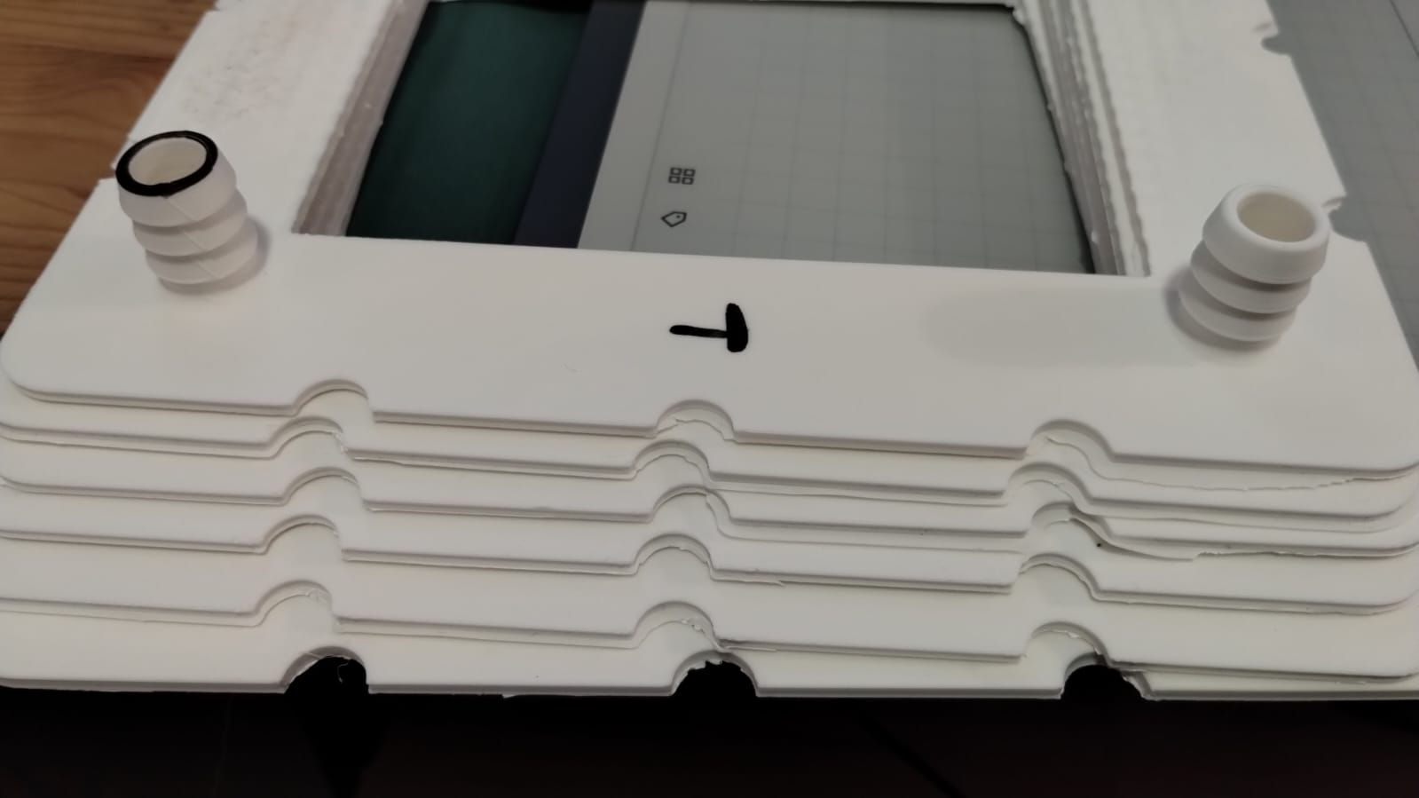
All flow frames are ready now. I'll have to wait a couple of weeks for some graphoil to cut the bipolar plate material that goes between the cells. Picture of the 6 finished flow frames below. I won't be running this with any active material, as I have no place to safely do so, I will just be testing for leaks to test the basics of the stacked design.
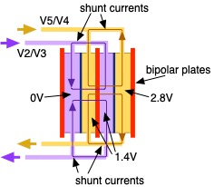
If ran with active material the expected voltage of this system with Zn-I would be ~3.6V and the current needed to charge it in a reasonable time would be around 3.5A. The system would produce around 12.6W, power capacity would be around 60Wh, would require around 1.5L of catholyte and 1.5L of anolyte. This would be enough capacity to run a raspberry pi for 12 hours.
-
Wow, amazing news! Especially being able to power some real world device sounds almost unreal. I guess you didn't factor in the pump consumption though.
About the safe place to run it in. Could you not just put it in a plastic container? I'm not sure if it's easy to buy large PP containers that are not IBC containers.
said in Designing the large-format cell:
About the safe place to run it in. Could you not just put it in a plastic container? I'm not sure if it's easy to buy large PP containers that are not IBC containers.
https://www.fasswulf.de/products/300-l-ibc-container-kunststoff-palette-150-50-un-zulassung
This LDPE container might work (after cutting the top off
 ) even if LDPE might not be ideal for mong term storage of triiodide.
 -
said in Designing the large-format cell:
About the safe place to run it in. Could you not just put it in a plastic container? I'm not sure if it's easy to buy large PP containers that are not IBC containers.
https://www.fasswulf.de/products/300-l-ibc-container-kunststoff-palette-150-50-un-zulassung
This LDPE container might work (after cutting the top off
 ) even if LDPE might not be ideal for mong term storage of triiodide.
@sepi The problem is not so much finding containers that can be used, but what happens if there is any issue. If some hose unhooks or breaks or there is a leak, it is not safe to have 1L of concentrated iodine solution spilled at your house. I live in an apartment, so I'm unable to test anything that involves meaningful amounts of active material, just because it's unsafe to do so as leaks would put me and my family's health at risk. To test a prototype like this - with a lot of potential for leaks and problems at high volumes - I would require a safe working space where leaks can be handled appropriately and without contaminating areas I am in contact with on a daily basis.
-
Don't know what you have there, but Target, Walmart, Home Depot, or even order from Amazon, Plastic storage bins. Just set the whole project in one. They come in clear so you can see in if there is a problem without removing the lid. If it spills, the fluid stays in the bin.
-
Don't know what you have there, but Target, Walmart, Home Depot, or even order from Amazon, Plastic storage bins. Just set the whole project in one. They come in clear so you can see in if there is a problem without removing the lid. If it spills, the fluid stays in the bin.
@Vorg A spill of a container full of charged electrolyte would off gas a lot of I2, which at those amounts is a big health risk. I sadly don't have a space where I could have that happen and then be able to ventilate that safely, nor do I have a spare room I could dedicate entirely to the project. So as far as I go, I will test with just water. We will likely get a space to do active material testing safely, but probably not until sometime next year. If any of you guys can do this testing safely and feel comfortable doing so, you can also take a shot! As with our kit, all the materials for this are open source.
-
@kirk Had a few thoughts that I hope are helpful or probing at least. Disclaimer, fluids are not my strength. I'd be happy to hear more about your insights or goals here.
Colleague pointed out to me that there are correlations for different porous media geometries (e.g., see Fig 4 & Equation 2.6 and a bit more surrounding context in this paper for details https://link.springer.com/article/10.1007/s11242-020-01423-y). So if you have the permeability (and make some assumptions), you can have some bounded estimates of the coefficient.
I'm trying to digest the utility of the Forchheimer part of Darcy-Forchheimer. For a first-pass estimate of pressure drop, I'm willing to bet using Darcy's law is sufficient to approximate pressure drop (maybe the computational expense is smaller, and it's more instructive for a general audience IMO).
Regarding flow distribution: relating flow to performance I think will be challenging (there could be a lot of cell performance that is determined by other electrode complexities beyond whatever "inertial flow" does to transport of active species).
I'd also note that measuring the pressure drop directly could be relatively easy. We've done them with cheap pressure sensors such as these before: link. Maybe that could be of use and might be a way to check for inertial effects?
In any case, excited for the next steps in the modeling!
Back with an update! Getting caught up:
@quinnale said in Designing the large-format cell:
Had a few thoughts that I hope are helpful or probing at least.
Thank you, I will take a look at that reference! A pressure-drop rig may be in our future...
@sepi said in Designing the large-format cell:
Wow, amazing news! Especially being able to power some real world device sounds almost unreal. I guess you didn't factor in the pump consumption though.
Aha yes, these pumps are at least a few watts each! However, they are capable of powering much larger cells/stacks that what we have here. In an optimized system they should consume no more than a 1-2% of round-trip energy efficiency, or so I've been told. We are a ways off from that, but this would still be a big step up for us in development, and we will have to learn/solve a lot of things... it is exciting though that it's starting to approach tangible power levels!
@danielfp248 said in Designing the large-format cell:
I sadly don't have a space where I could have that happen and then be able to ventilate that safely, nor do I have a spare room I could dedicate entirely to the project.
I have a suitable location for this which is isolated and away from living spaces; I will be carrying out the first cycling tests of the large-format cell there. For reasons pointed out, although Zn-I is a relatively safe chemistry compared to say all-V or Fe/Cr, large quantities of corrosive liquid are always a risk, plus the peculiarities of iodine (which, of course, I'd rather have to deal with than say, bromine!). Zn-I is relatively accessible and well-behaved, which is why we're using it, but we'd really like to figure out some other alternatives, which we are documenting here: https://fbrc.nodebb.com/category/6/electrolyte-development.
-
I am in the process of building the test rig for the large-format cell. It will also be able to handle larger area cells, as well as stacks, and cover us for a long range of development. Just to be clear, it will be an R&D system, not something aimed at end-use! I am using conservative initial engineering design, so it will be overbuilt a tad.
The rig will be capable of:
- starting/stopping, speed controlling, and monitoring the individual power consumption of two mag-drive polypropylene centrifugal pumps (designed for use in chemical industry, currently using 6 L/min models).
- circulating two independent fluid loops through >= 1L reservoirs and a large-format RFB cell (the one detailed already in this thread)
- Charge/discharging single cells and stacks (of at least several cells), using a DC-DC configuration for now (we will be discharging the flow cell into another DC device, like an old lead-acid battery - I have a lot of those where I'm at now). For now we will be using the OwnTech Twist for this, because it is OSHW and I know the developers, and so they have to help me debug it

- all the power electronics will be in a proper enclosure and DIN mounted, with an emergency stop
- temp monitoring of system: thinking of monitoring ambient, cell (somewhere on the current collectors?), the outside of each reservoir, the pumps (which have thermal protection, allegedly)
- remote monitoring of the system with a Raspberry Pi + webcam. This way we can have a leak alert as well as monitor the reservoir levels independently (it is hard to find a sensor that you can put in the tank that is chemically compatible - also, want to minimize hols in the tanks!)
- I am shoving the whole thing into secondary containment and adding a fume extraction system for safety during tests
This is a non-exhaustive list - I will keep this thread updated as I build it, and add a schematic so it's clearer.
-
Here is a rough schematic of the test bench, showing where AC, DC, information is flowing:
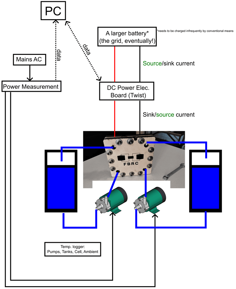
The idea of using a DC-DC converter to source and sink current into a larger battery came from the OwnTech community. Charging a battery at low voltage (1 V) and high current (>1 A) is easy, you can just use a power supply, but discharging that while measuring performance is hard; you have to have large power resistors and shunts, etc. in lieu of a proper battery cycler (which is thousands of EUR). I had originally wanted to go straight to using the Twist as a DC-AC system, sourcing and sinking from the grid, but at a single cell voltage, we are not ready to do that yet.
Why I did not put pressure or flowrate sensors in:
I tried to find flow measurement devices but could not find something affordable that was satisfactory that could be used with zinc-iodide or similar electrolytes. Acrylic rotameters or glass/metal ones could be used (along with pressure sensors) in a flow loop of pure water to test pressure drop vs. flow rate. However, this seemed like a distraction away from making our first tests with the large-format cell with the zinc-iodide chemistry. We can always measure the approximate flowrate of the pumps by dispensing water through the cell into a bucket and weighing it after a fixed time period. FWIW, these pumps are supposed to be 5-6 L/min.
Another note on flow control:
In any case, in a real flow battery in the field, I am not sure whether it is a good idea to rely on explicit flowrate measurement in the control system. Maybe a flow switch, like “is there flow or not-→ output true or false”, to avoid turning the stack on without electrolyte inside, but not a sensor giving readings in L/min or similar. Flowrate sensors that are chemically compatible are expensive and another thing that can break.
What we care about is having sufficient mass transfer of electrolyte through the graphite felt (lowers the overpotential from mass transfer, improves efficiency), but not too much flow (reduces efficiency from needless pressure drop, improvement of mass transfer by pumping yields diminishing returns). If you measure the power consumption of the pumps (easy, cheap, and robust: a shunt or current clamp), and the current/voltage data from the stack (which is already available), a properly designed control algorithm should be able to determine the ideal flowrate (or close to it), without having to know the precise value of the actual flow. Control systems engineers to the front on this one, please!
All the parts for this rig have been ordered and are in the process of arriving. After @danielfp248 finalizes leak testing (already completed at the single cell level) with his large-format cell, he is going to send it to me. I will run the initial tests with the zinc-iodide electrolyte we optimized with the dev kit.
The funding for developing the large-format cell and the test bench needed to characterize it comes from the NLnet grant we received, we are very grateful for their support!
-
First stack assembly. This stack contains two cells. My screws weren't long enough so I had to sacrifice using one of the birch wood endplates to have it seal. Hopefully it doesn't leak!
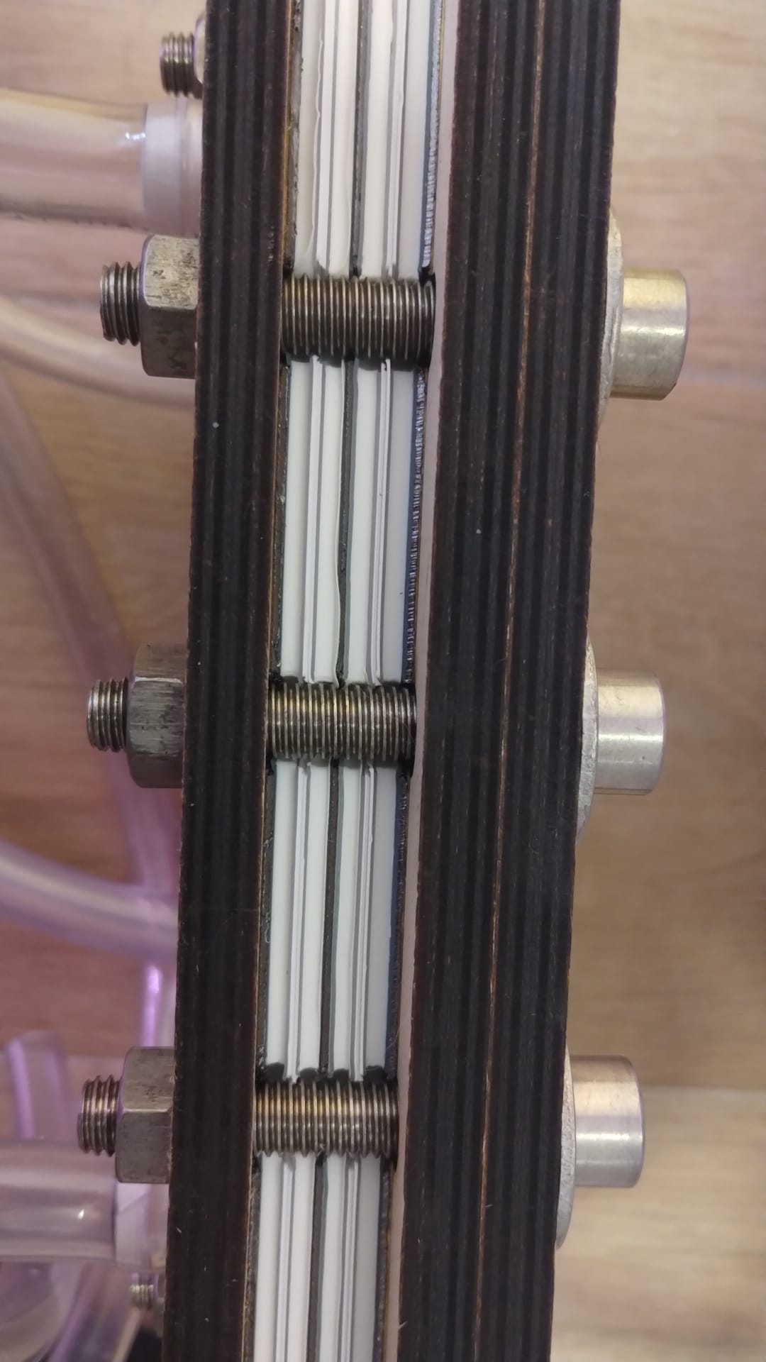
I will keep you guys posted. I will leak test this and then mail it to kirk for testing with real electrolyte.
-
This circulated without any leaks, even lacking one of the endplates.
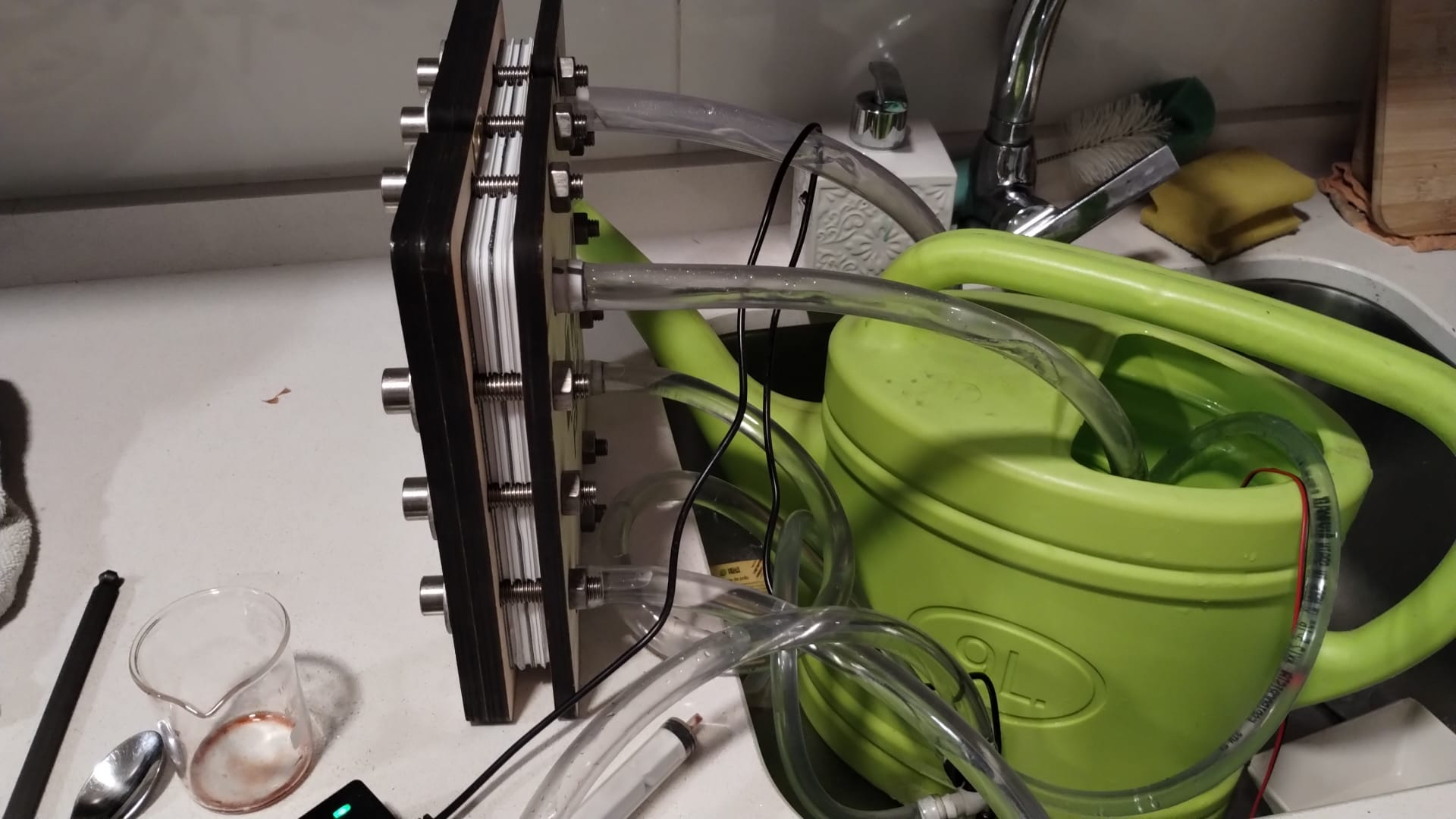
I will try doing a 3 cell stack, removing one of the other birch wood end plates.
-
Update after some work!
I have built the test bench, although there remains some work to do. Unfortunately, I haven't been able to perform any charge-discharge cycling yet, as a large order I had of chemicals and plumbing fittings I ordered almost 6 weeks ago (from the Netherlands, and going to France) hasn't shipped yet. Nevertheless, I have been able to make progress in the meantime in preparation for their arrival.
The large-format cell arrived from Daniel in the mail, and I got it connected to the centrifugal pumps I had waiting.
Plumbing
I fabricated some reservoirs out of off-the-shelf laboratory containers and bulkhead fittings (1/2" or ~12 mm size), all polypropylene. I just drilled holes into the containers (a step drill bit is great for drilling the thin plastic containers). I didn't need any adhesive or melting to seal the fittings, the provided silicone gaskets worked well (though time will tell if they stand up to charged triiodide solution.) I am using only 1 L containers right now to keep the volume to a minimum; this setup can also work with larger reservoirs.
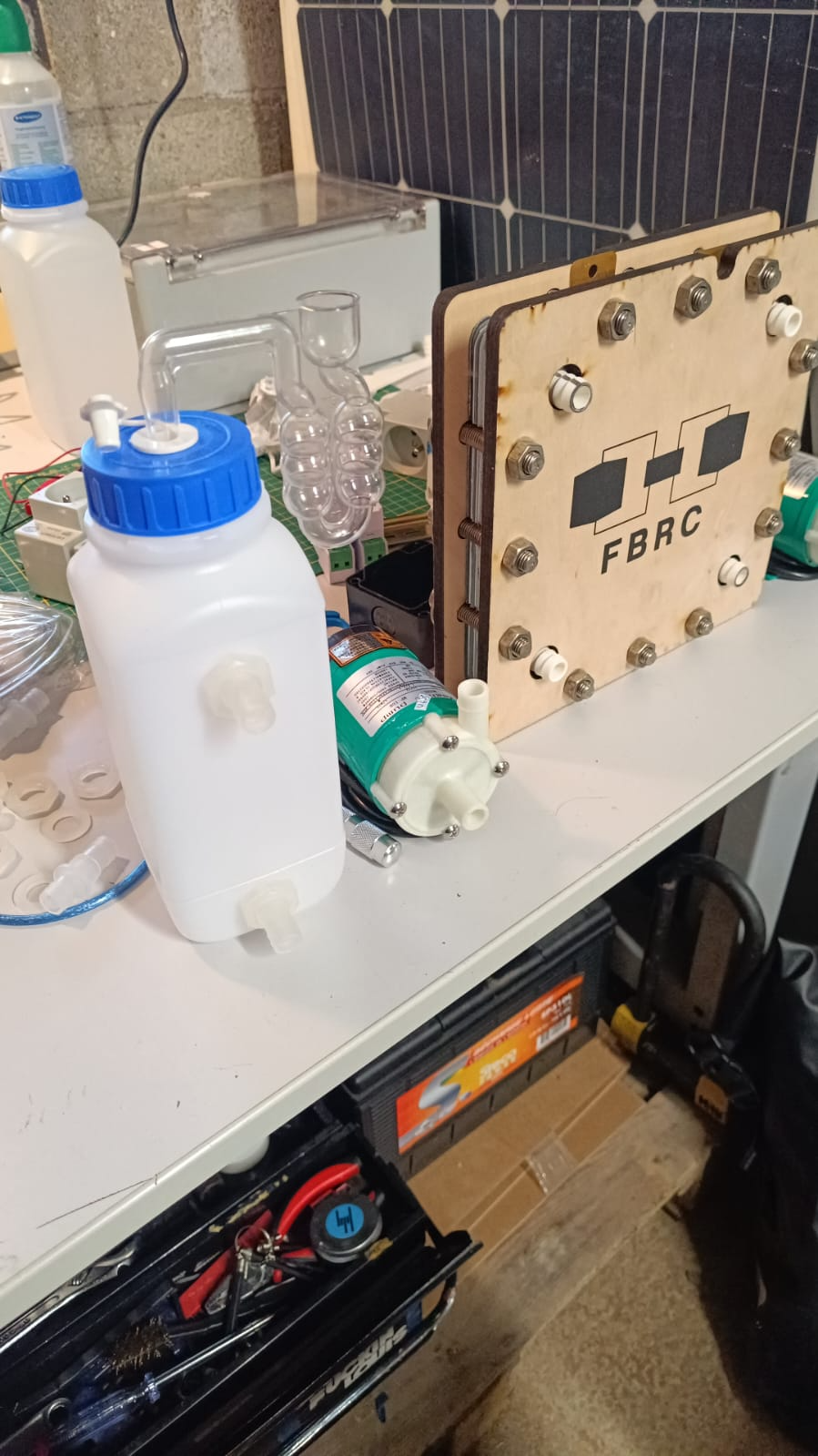
I also mounted home-brewing grade airlocks to the tops of the reservoirs, the idea is to keep the reservoirs at ambient pressure and also monitor if there is any gas formation (we can remotely monitor with a webcam or similar). If accidentally we make some hydrogen, for example, we want it to vent immediately instead of building up pressure. The airlocks are empty right now since I was not doing any charge/discharge testing.
Here is a video of water running through the flow loop: https://spectra.video/w/69m6bYX3ym3rQQuz7hQk5t
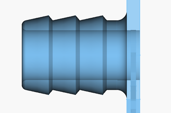
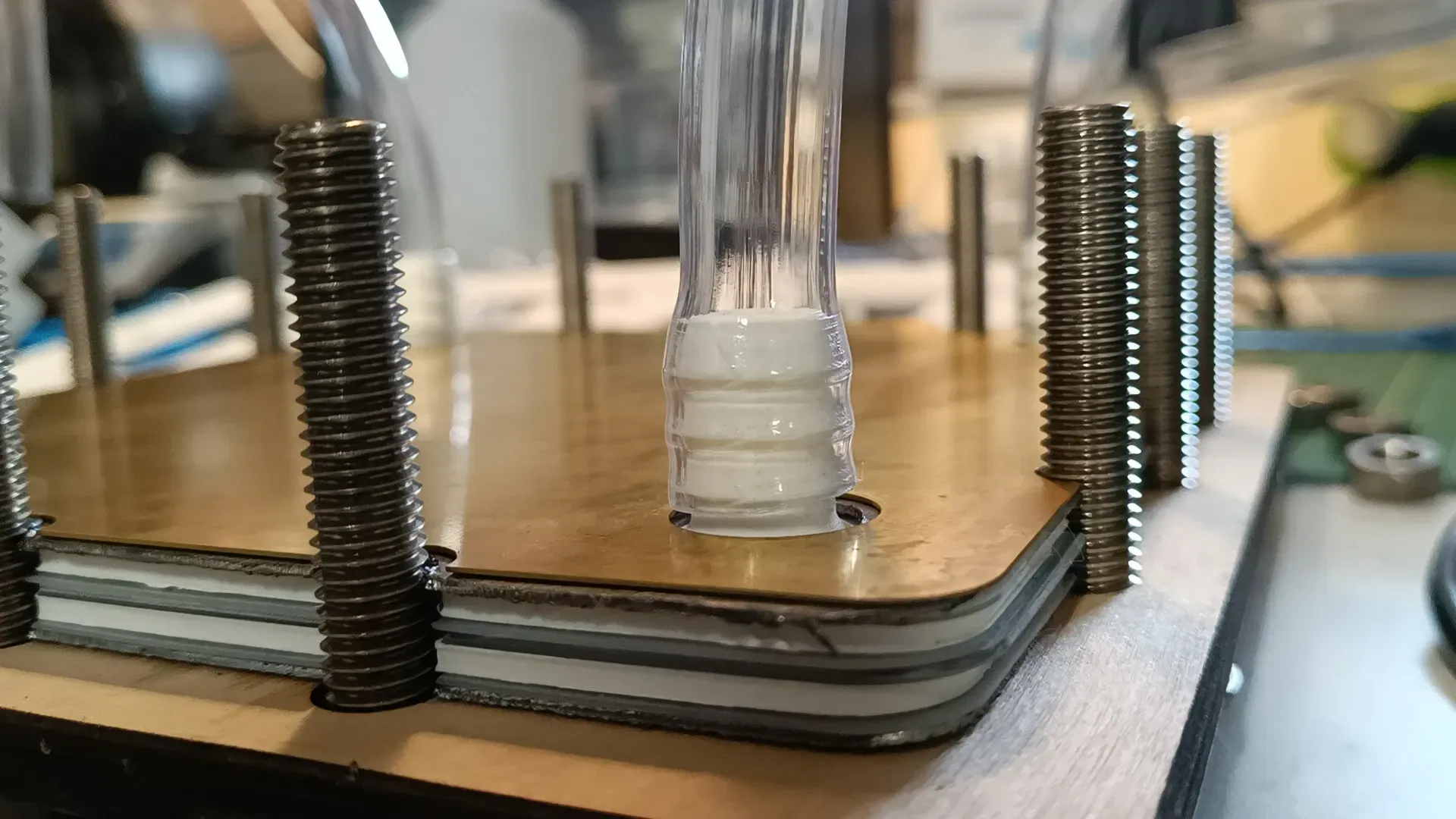
Right now, we are using barbed connections everywhere, and it seems to be working. 1/2" PVC tubing was used for all connections. This tubing was too thin though, and easily kinked. It was also very hard to repeatedly take on/off from all the fittings. Hopefully the all-iron chemistry will allow us to use tubing that's easier to work with, like silicone. Also, this is more of a problem for testing, and not long-term usage. It's great that simple barbed fittings are working for now since they are simple, cheap, and printable.
Here is the current barb design for the flow frames:
Power Electronics
As you can see in the video I have all the relevant electronics connected for controlling the pumps, though it's not yet DIN mounted in the electrical cabinet. I am working with mains (240 V) AC, so I have installed a circuit breaker and emergency stop, and plan to mount everything inside the cabinet once the configuration is final. There is a Shelly energy monitor connected that monitors the power consumption of the pumps; it also provides a relay output that can switch the pumps. I am able to remotely stop/start the pumps with this setup, which is great, and it should be trivial to allow, say, the OwnTech board to adjust the pump speed and monitor the pumps power consumption. With this, we will be able to get a better idea of what system level efficiency looks like. These pumps (Haiyi MP-6R / 10RN, also see this), or similar - confused on the branding) were drawing about what they said on the datasheet, a little over 6 W each.
The concept I had planned for the charge/discharge tests still looks like it should work, but there is more development effort to use the OwnTech board than I had planned on. See the discussion I've been having at https://forum.owntech.org/t/fbrc-flow-battery-power-electronics-and-pump-motor-control/14. I need to change some variables in the PID loops of the standard boost/buck converter programs to control for I_low or I_high, rather than V_low and V_high (ie, to convert from potentiostatic to galvanostatic mode, constant-voltage to constant-potential). This seems easily possible but it's going to take a bit longer than I'd imagined because I'll need to debug it, likely working with some existing batteries like lead-acid first before switching to use our cell. I have gotten the OwnTech board and associated software working though, and it seems like a great platform to use for the project going forward.
In the meantime I can use a MightyWatt electronic load + a laboratory power supply that I already have, that is in the process of being sent back to me in the mail.
Cell Assembly
The basic principle we have to seal the cell works. It is essential to use two 12mm endplates on each side in order to achieve adequate sealing. A single 24 mm endplate would also work, but we weren't able to source this.
Notes:
- Separator needs to have smaller holes for the ports, to match the gaskets
- Thicker PVC tubing needed to avoid kinks, tubing is hard to work with. All-Fe chemistry may allow for easier tubing (e.g. silicone)
-
In preparation for cycling with ~1 L quantities of electrolyte, I have also sourced a makeshift fume extractor that I will place over the assembly during cycling to vent to the outside.
I also have obtained a combination pH/conductivity probe to characterize the prepared electrolytes and assist us with modeling (once the chemicals arrive...).
-
Here is a video of assembling the large-format cell.
https://spectra.video/w/m9RKg1QWrFdkkn9qUBFMTS
FYI, you are meant two use two endplates per side (I used one here), I intentionally left the graphite felt out as this was for leak-testing, and the cell is missing washers on one side. The video illustrates the basic process of assembling our cell and how it is designed and seals. All the design files are available at https://codeberg.org/FBRC/RFB-large-format-cell.
The setup is essentially there, waiting on chemicals and sorting out the power electronics set up and we should be able to run our first real charge/discharge tests with this large-format cell!
The work to get to this point has been supported by the NGI0 Entrust Fund, a fund established by NLnet, to whom we are very grateful!
-
 V victor_tokarev@twiukraine.com shared this topic

