Think of this as your global discovery feed. It brings together interesting discussions from across the web and other communities, all in one place.
While you can browse what's trending now, the best way to use this feed is to make it your own. By creating an account, you can follow specific creators and topics to filter out the noise and see only what matters to you.
Ready to dive in? Create an account to start following others, get notified when people reply to you, and save your favorite finds.
Idk if it is the best place to post, tho I did not want to do this in Codeberg, as to avoid unecessary text in development process
So I would love to contribute into FBRC, I can help you with electronics, as well as firmware development, especially if you would like to develop more standalone device, in C/C++ or Rust (preferable, it just safer :P). I can also help to define/write unittests for the firmware
Also my proposition is to create a [matrix] room to create a instant messaging possibility
@H4K1 no need to build the flow battery and test chemistry to help the project out! You can also build and test just with water, especially the larger cell we'll build. But if you can do CI/CD and firmware now then that's great! You'd be the only one on the project now with those capabilities, so a huge bonus. It will help make a framework that we'll benefit from as the project advances and hopefully save us some time as we improve and develop, so we can focus on what we're all best at and enjoy!
Track: Energy: Accelerating the Transition through Open Source
Room: H.2214
Day: Sunday
Start: 10:55 (Brussels)
End: 11:15
Video only: h2214
Chat: Join the conversation!
Daniel and Josh will be presenting on our work. Looking forward to connecting with the many cool projects in our devroom and others, as well as hopefully meeting with other @nlnet@nlnet.nl and @ngizero@mastodon.xyz projects!
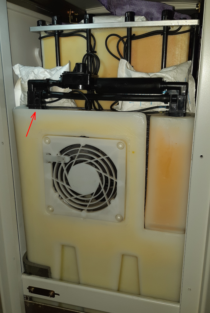
It’s time for a review of the second year of operation of our Redflow ZCell battery and Victron Energy inverter/charger system. To understand what follows it will help to read the earlier posts in this series:
Go With The Flow (what all the pieces are, what they do, some teething problems)
Hack Week 21: Keeping the Battery Full (an experiment in working around the limitations of a single ZCell)
TANSTAAFL (review/analysis of the first year of operation)
In case ~12,000 words of background reading seem daunting, I’ll try to summarise the most important details here:
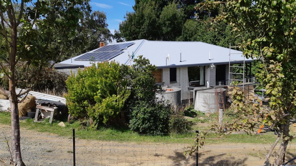
We have a 5.94kW solar array hooked up to a Victron MPPT RS solar charge controller, two Victron 5kW Multi-Plus II inverter/chargers, a Victron Cerbo GX console, and a single 10kWh Redflow ZCell battery. It works really well. We’re using most of our generated power locally, and it’s enabled us to blissfully coast through several grid power outages and various other minor glitches. The Victron gear and the ZCell were installed by Lifestyle Electrical Services.
Redflow batteries are excellent because you can 100% cycle them every day, and they aren’t a giant lump of lithium strapped to your house that’s impossible to put out if it bursts into flames. The catch is that they need to undergo periodic maintenance where they are completely discharged for a few hours at least every three days. If you have more than one, that’s fine because the maintenance cycles interleave (it’s all automatic). If you only have one, you can’t survive grid outages if you’re in a maintenance period, and you can’t ordinarily use the Cerbo’s Minimum State of Charge (MinSoC) setting to perpetually keep a small charge in the battery in case of emergencies. As we still only have one battery, I’ve spent a fair bit of time experimenting to mitigate this as much as I can.
The system itself requires a certain amount of power to run. Think of the pumps and fans in the battery, and the power used directly by the inverters and the console. On top of that a certain amount of power is simply lost to AC/DC conversion and charge/discharge inefficiencies. That’s power that comes into your house from the grid and from the sun that your loads, i.e. the things you care about running, don’t get to use. This is true of all solar PV and battery storage systems to a greater or lesser degree, but it’s not something that people always think about.
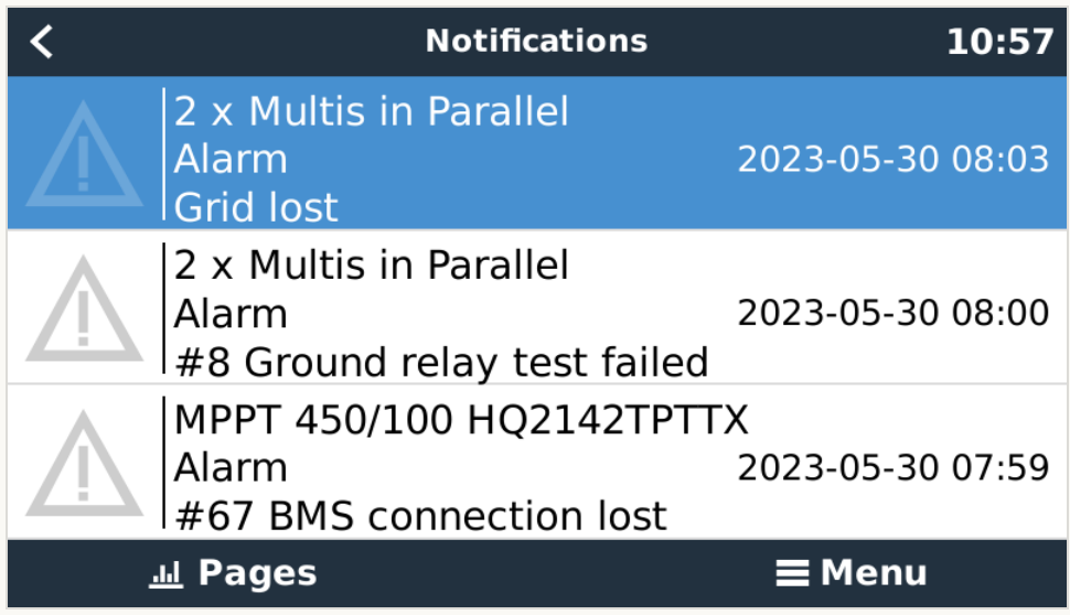
With the background out of the way we can get on to the fun stuff, including a roof replacement, an unexpected fault after a power outage followed by some mains switchboard rewiring, a small electrolyte leak, further hackery to keep a bit of charge in the battery most of the time, and finally some numbers.
@kirk I hadn't spotted this years update to @tserong system - Thanks for the pointer! Bummer about redflow going under. We've gone for the riskier lump of lithium strapped to the outside of the house (Just as well Snug never has bushfi...oh). Can confirm that the #tasnetworks cablepi objects when we're off-grid. Reminds me I need to chase installer as our grid-tied inverter (on the essential load side) rightly objects to the 55.1Hz Sonnen runs at when in island mode - Want to decrease this.
We are migrating our forum hosting to @nodebb@fosstodon.org to try to engage with the fediverse more broadly.
You should be able to reply to this topic from your ActivityPub-enabled client, upvote ("favorite" on Mastodon), edit your posts, etc. You can also create a separate account directly on the forum if you like.
You can create topics to ask questions or start discussions in @general-discussion and @Comments-Feedback categories directly via ActivityPub by mentioning those handles. You can also follow forum users directly, like myself at @kirk@fbrc.nodebb.com (this account)
We hope this will allow us to get better feedback and insights into the development of our open-source flow battery!
Publishing my and @andrew 's list of flow battery companies as a public resource! Over 50 enterprises as of current writing. Trying to loosely keep track of who's doing what with which chemistries.
My original idea was to create a flow battery without Vanadium that would contain no metal deposition reactions on either the anodic or cathodic sites. This would be a true flow battery, in the sense that energy capacity would be completely decoupled from power capacity. It would also be compatible with a symmetric electrolyte which would allow the use of microporous membranes. There is currently no low cost flow battery – to the best of my knowledge – that fulfills these criteria, outside of Fe/Mn (with Fe/Cr and V being the only options).
My original idea was to use easily sourced FeEDTA and MnEDTA for this purpose. However it became clear that there are important solubility issues with FeEDTA and MnEDTA plus significant stability issues related with the Mn3+ EDTA chelate, which prevented this battery from actually working. While both FeEDTA and MnEDTA had been used in different flow batteries, no one had put them together on any published research — now I know why.
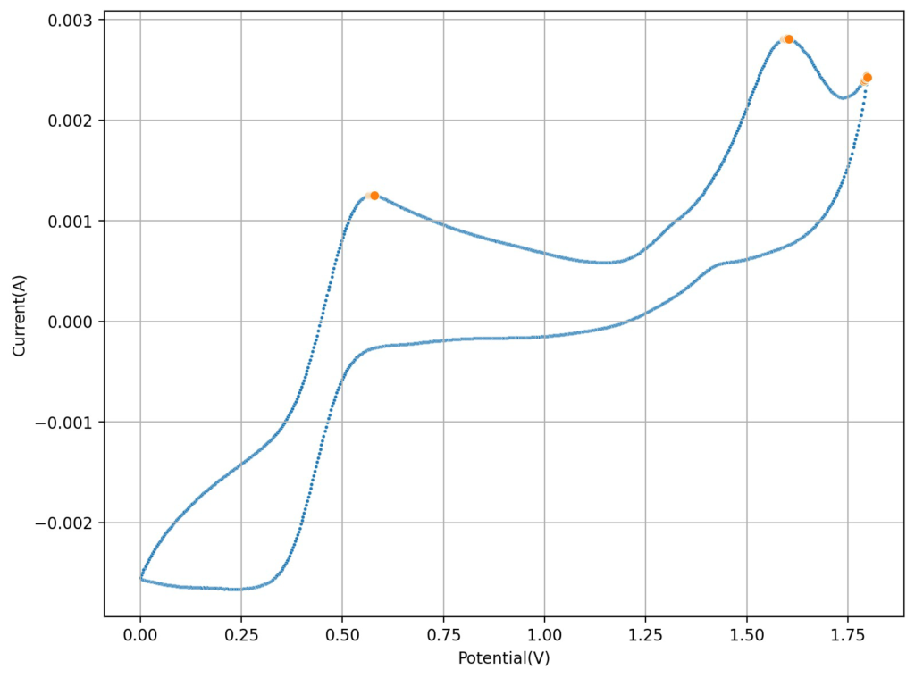
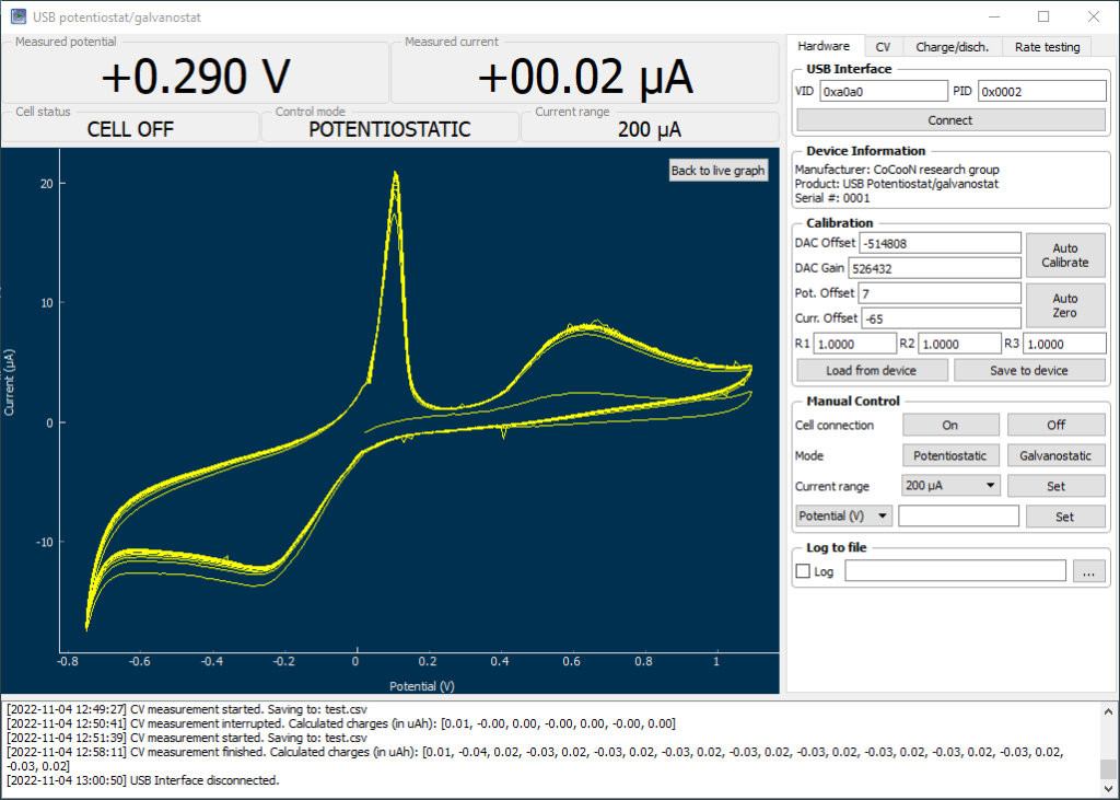
Cyclic voltammetry of FeCl3 1.5M + MnCl2 1.5M + 3M HCl (concentrations are approximate). Reference electrode was Ag/AgCl, glassy carbon working electrode, graphite counter electrode. Scan rate was 10mV/s.
However, there was a paper published in 2022 that was able to use a symmetric Fe/Mn chemistry by employing Fe chloride and Mn sulfate in an acidic media with a special proportion of sulfuric acid and hydrochloric acid. I wanted to try this out to see if I could actually get an Fe/Mn chemistry that worked. The paper goes into the importance of the hydrochloric acid to generate stable Mn3+ species, but doesn’t say anything about the importance of the sulfuric acid, so I decided to try a hydrochloric acid only approach for starters and see if the CVs showed reversible Mn chemistry.
The first CV I carried out is shown above. This solution was prepared by using 5mL of 15% HCl, 5 mL of 40% FeCl3 and 3g of MnCl2. You can see the reversible reaction for the Fe with a standard potential near 0.45V, you can also see an Mn oxidation peak near 1.6V with no evident reversibility (no reduction peak). This is classic for the formation of MnO2 and its subsequent conversion back to Mn2+ with generation of Cl2 in concentrated hydrochloric acid. Gas bubbles on the working electrode were also evident, which further supports this hypothesis.
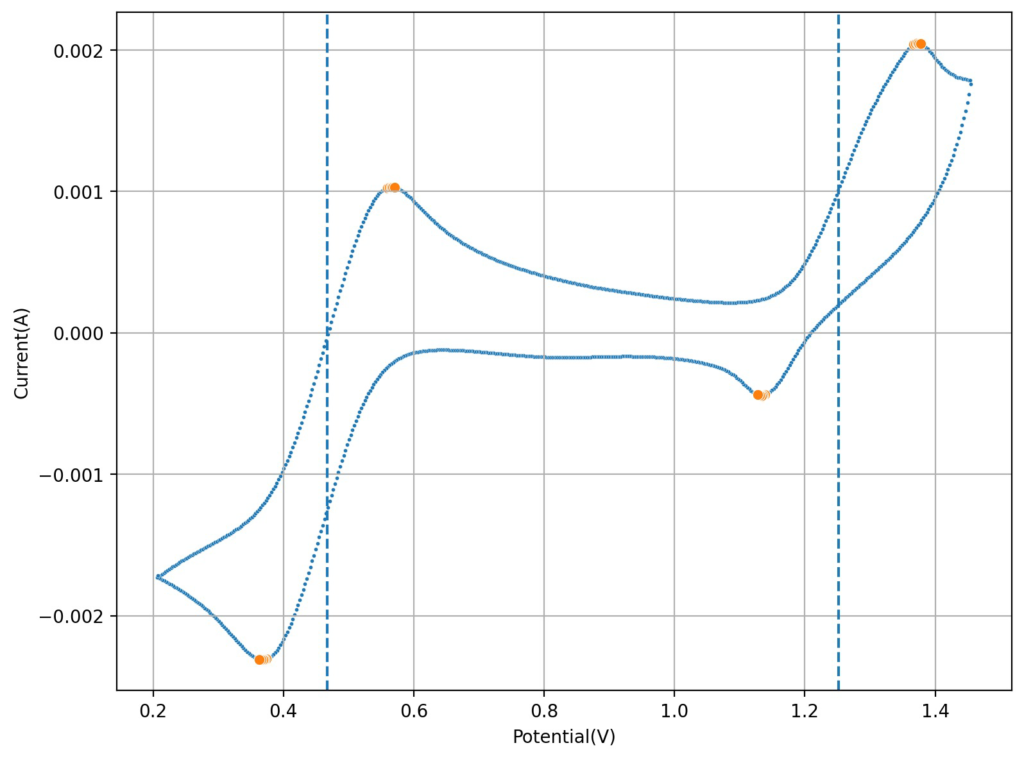
Cyclic voltammetry of FeCl3 1.5M + MnCl2 1.5M + 0.6M HCl (concentrations are approximate). Reference electrode was Ag/AgCl, glassy carbon working electrode, graphite counter electrode. Scan rate was 10mV/s.
I then tried lowering the concentration of the HCl to see what would happen to the CV. Interestingly enough, when going with a 0.6M concentration, I saw the appearance of a reversible reaction with a standard potential near 1.25V, which is near the potential that is mentioned on the paper. This peak also shows significant reversibility, with the corresponding reduction peak appearing near 1.15V. The difference between these two standard peaks is also 0.775mV, which is close to the open circuit potential reported for the flow battery within the paper I mentioned before. This solution was 1mL 15% HCl, 3g MnCl2 and 5mL of FeCl3 40%.
Upon charging, acid will become depleted from the cathodic side, which might be why the sulfuric acid was used on the paper to generate proper cycling (as MnO2 would start forming if the pH became too basic). Interestingly enough, volumetric capacities aren’t mentioned in the paper (just mAh of charge). Using their values of 5mL of volume per side (total volume of 10mL) their discharge capacity goes from 1-2.5Wh/L, which is 10x lower than the standard for Vanadium batteries. This means that – while the Mn3+ chemistry is reversible – very little of the Mn is actually accessible (less than 10% at a 1M concentration).
The acid balance here is fundamental, so you likely need just the right amount of HCl to make Mn3+ stable, but not enough as to make the oxidation of Cl– to Cl2 very favorable. If possible I would like to stay with a battery with only chlorides, as the inputs are easier to source (sulfuric acid is hard to get in many places), so I will try to cycle the above chemistry soon as see if it is actually feasible. On another note, Mn3+ reacts with cellulose quite quickly, so I will have to use a proper microporous separator – like Daramic – instead of the photopaper I have been using for Zn/I experiments.
Things are not looking very good for an Fe/Mn chemistry.
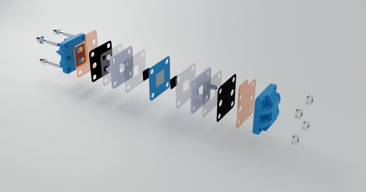
Over the past year, I’ve collaborated with my colleagues Kirk Smith, Sanli Faez, and Joshua Hauser on developing an open-source flow battery design and kit. Our aim is to make it feasible for most individuals to construct this flow battery with readily available parts that can be either purchased online or fabricated affordably. We’re targeting a price point below 1000 EUR, inclusive of the potentiostat, to ensure accessibility.
The kit encompasses all necessary components for constructing and utilizing a flow battery for research and development purposes. This includes the battery itself, pumps, electronic components for pump operation, potentiostat, tubing, reservoirs, and a jig for orderly arrangement. Presently, similar setups cost upwards of 9000 EUR, hence our aspiration for significant cost reduction.
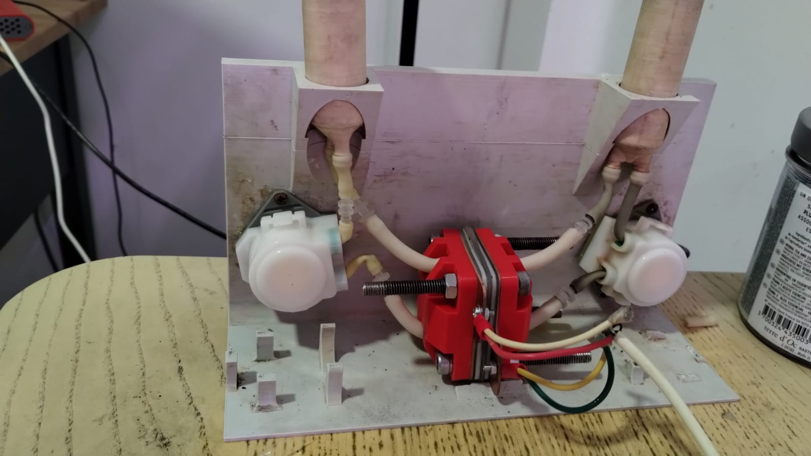
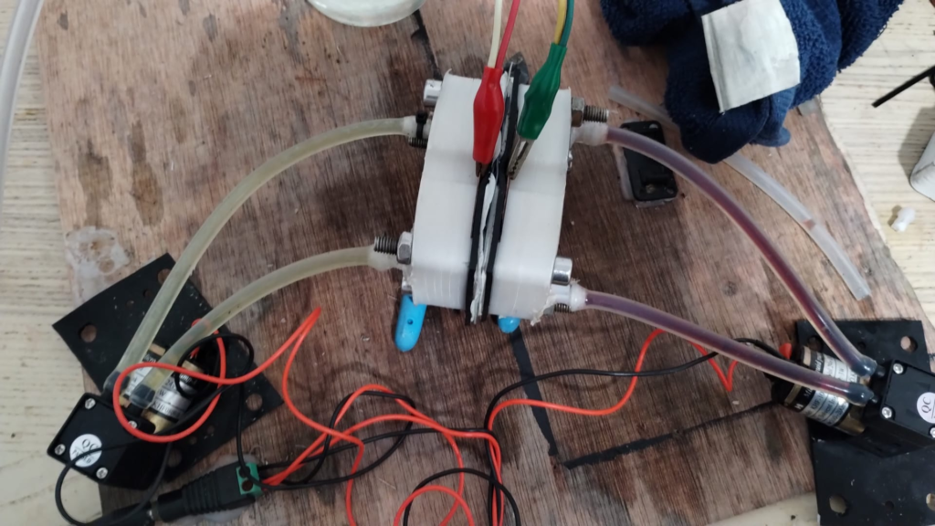
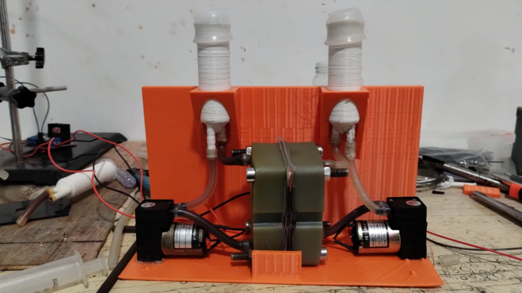
A polypropylene FDM printed prototype being tested with Mn/Fe chemistry. This particular test was done without reservoirs, on close circuit circulation to easily detect any leaking.
Image of one of our latest prototypes. This features polypropylene FDM printed reservoirs, a resin printed cell body and a PLA FDM printed jig.
Throughout this endeavor, we’ve explored various fabrication methods for our designs, employing FDM and resin 3D printing techniques alongside traditional CNC fabrication. While all three methods are viable, our experiments indicate that the most optimal results are achieved through traditional milling.
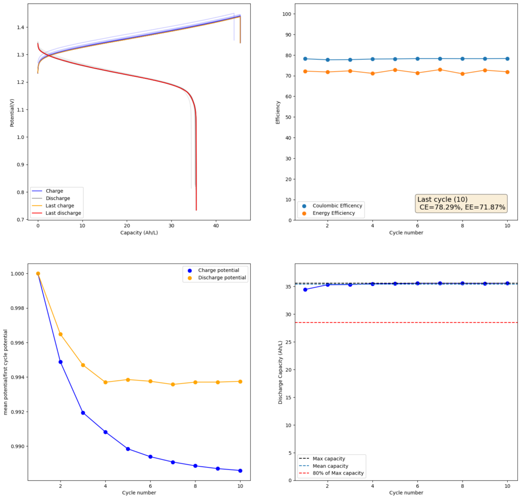
Charge/discharge cycle using photopaper separators and the Zn-I chemistry using the open source flow battery design.
Validation of our design involved utilizing a low-cost photopaper separator and Zn-I chemistry. We’ve achieved successful charge/discharge cycles at capacities ranging from 20-40 Wh/L. However, long-term cycling validation remains ongoing, as we’ve only been testing the final design for approximately a month.
Our design will be presented at the Flow4UBattery Event in Eindhoven, Netherlands, on April 8-9, 2024. You can register here for free, which also includes complimentary lunch (so please make sure you intend to attend if you subscribe). Day 2 of the event will feature a workshop where participants can assemble a flow battery themselves using the design from our kit. Additionally, we’ll be giving away 5 complete kits during the event, each including mystat potentiostats. We’ll also have a fully assembled kit doing cycling so that you can see the fully assembled kit in action!
After this event, we will look into selling these kits online, with all proceeds going towards the development of higher capacity kits with the objective of reaching an open source flow battery stack within the next 2 years. We will also be publishing the full designs and bill of materials online, so that anyone can create their own too!
On my last post, I showed the results of charging/discharging a flow battery using a ZnCl2+NH4Cl+KI electrolyte using 4 layers of Daramic as a membrane. However, while Daramic is a low cost material, it is not easily accessible for DIY testing at this moment. For this reason, I wanted to run some tests on materials that are easier to source than Daramic.
I looked for materials around my house that had similar porosity (0.1-5um). I tested several different papers that I had around but none of them worked very well. The porosity of most traditional printer papers is high, with most having 10-20um pore sizes. This means that you need many layers to prevent fast self-discharge from migration of the triiodide across the membrane. Additionally, the papers lost structural integrity quite easily.
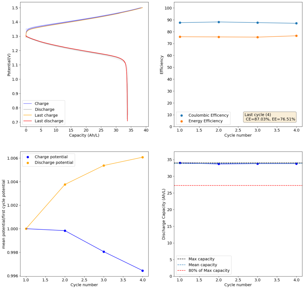
Test using a 2m ZnCl2 + 2m NH4Cl + 4m KI electrolyte at a current density of 20mA/cm2. Four layers of matte photo paper were used as separator.
Finally, I stumbled upon matte photo paper as a potential solution. This paper has much lower porosity with <5um pore sizes. Some of these papers might even have pore sizes that are below 1um. This is important for printing photographs, as low pore sizes implies that there is less bleeding of ink when it is applied to the paper, although ink needs to be applied much more slowly to the material (reason why printing with these papers is really slow).
For my initial test, I used 4 layers of matte photo paper. The paper does have a substantially higher ohmic resistance compared to Daramic, so I had to lower the current density to 20mA/cm2. I did 4 cycles of charge/discharge that you can see above (I only did 4 because the lower current meant cycling was quite slow). The CE of 87.54% and EE of 75.72% with a capacity of 33.8 Ah/L shows that photo paper is definitely a good choice for at least the short term cycling of these devices.
On inspection, the photo paper did not show any evident degradation although dendrite penetration happened just as much as it did with the Daramic separator. The separator was also completely black, fully permeated by the catholyte solution which contains triiodide in solution when charged.
After concluding my work with the Fe-Mn system, I still wanted to find a system that I could use to build flow batteries. With my new flow battery systems – which I got thanks to my colleague Kirk – I have been able to test different chemistries to come up with the most practical approach for an actual DIY flow battery.
To build such a battery, I first started with a list of requirements:
Easy to find chemical supplies.
Voltage at least equal to vanadium flow batteries (>1.2V).
Energy at least equal to vanadium flow batteries (>25Wh/L).
Efficiencies at least equal to vanadium flow batteries (>70% EE).
Mildly acidic or basic (no strong acids or bases).
Ideally uses a microporous membrane (no need for ion exchange membranes).
Long term cycling stability (>1000 charge/discharge cycles).
There aren’t a lot of systems that can comply with all the above requirements. One of the few that seemed plausible was the Zn-I system. In this system, Zn2+ is reduced to Zn metal on the anode and I- is oxidized to I2 (which quickly gets converted to I3–) in the cathode. The Zn can be plated with a good density, often at more than 100mAh/cm2 of cathode when using carbon felts.
Results of a 1m ZnBr2 + 1m KCl + 2m KI flow battery using 4 layers of Daramic as the microporous separator, carbon felt anode and cathode with a copper sheet as the anode current collector and a graphite plate as the cathode current collector. The current was 40 mA/cm2
Both the Zn/Zn2+ and I–/I3– couples are kinetically very fast – allowing for large currently densities – and have large energy densities. In particular, the solubility of their salts is quite large, so achieving solutions with concentrations >6M is not a problem. At 6M, the theoretical capacity of the battery is around 156Ah/L, rivaling even LiFePO4 batteries.
There are two main problems with this system. The first is the formation of Zn dendrites in the anode, which shorts the battery, and the second, the formation of solid I2 in the cathode after a state of charge of around 66%, which interrupts flow through the battery and causes it to fail. This means that the max State Of Charge (SOC), is often limited to 66% even if no dendrites are present (which is a big if).
Luckily some publications already exist showing that we can sacrifice some efficiency to overcome some of these issues. For example, this paper uses a polyolefin microporous membrane to obtain flow batteries that work at very high current densities and which can “cure” from overcharging due to the constant “leak” of iodine into the anode side. Since the same electrolyte is used as catholyte and anolyte, there is no problem with changes in composition as a function of time.
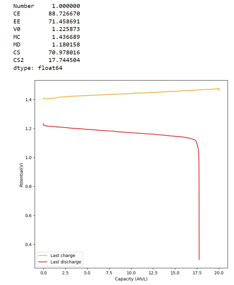
I decided to use this paper as a template and try reproducing their results. I started by making a 2m solution (this is moles of solute per kg of solvent). You can see my results in the first image above. I was able to obtain a charge of 19.3Ah/L since the 2m solution comes out to approximately 1.5M (because the final volume is larger), this comes out to an SOC of 48%. Trying to charge the battery higher ends up generating I2 solid in my cathode and therefore killing the battery (as no flow becomes possible).
My current was also lower (40mA/cm2 vs 80mA/cm2) because my potentiostat overheated at higher densities (which means I need to build some heatsink to test these current levels). Note that I also ran at higher mL/cm2 since my closed loop is exactly 1mL/cm2 while the paper runs at half of this, meaning that their Zn accumulation per electrode area is half. I also used 4 layers of Daramic to match the thickness of their polyolefin membrane (around 900um).
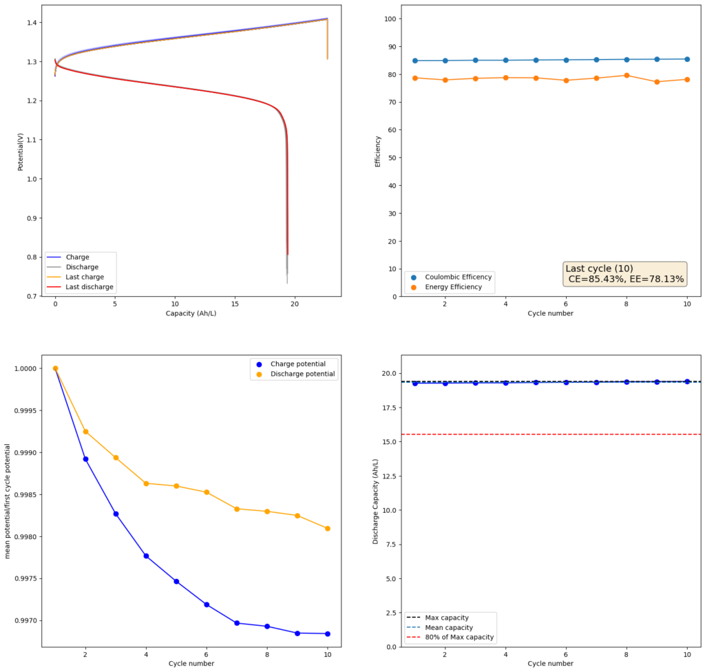
Results of a 1m ZnCl2 + 1m NH4Cl + 2m KI flow battery using 4 layers of Daramic as the microporous separator, carbon felt anode and cathode with a copper sheet as the anode current collector and a graphite plate as the cathode current collector. The current was 40 mA/cm2
The CE and EE values are pretty decent, but loses from crossover of the microporous membrane are evident. These loses have an advantage though as iodine that permeates the membrane dissolves any Zinc dendrites that might be perforating it, so the battery cycling is very stable.
Since I didn’t observe any gain in SOC due to the presence of the Bromide, I tried to reproduce the results using a lower cost mixture of ZnCl2+NH4Cl+KI. This time I also increased the concentration to 4m to see if I would get a proportional gain in the capacity. The results of this test are showed in the second image in this post.
As expected, there is a drop in the CE and the EE of the device (as more crossover can happen at longer charging times) but the capacity of the battery increases proportionately as well. I was able to charge to double the amount, but the discharge capacity did not increase as much, due to the drop in efficiency. This time I was able to get 35.5Ah/L out of the battery, which is an SOC of around 42%. This is however, already higher than a Vanadium flow battery normally offers (~25Ah/L). Note that higher concentrations are not possible in my system with 4 layers of Daramic as dendrites will start fully crossing the separator at a density of around 56mAh/cm2 (while charge density in the last test is 45.45mAh/cm2).
As you can see, the Zn-I system with a microporous membrane is great. It is stable, has decent energy density, supports large currents and does not require an expensive ion exchange membrane. There are certainly potential improvements to increase the available SOC, but even at the current levels, the system would already be useful in practical applications. Higher separator thickness could also increase the CE and EE of the battery system, without much compromise to the ohmic resistance. Small modifications to the separator – such as adding a carbon coating – can also increase its selectivity and reduce the extent of Iodine migration. Note that you do not want to completely stop it as stopping it leads to dendrites shorting the battery.
I also tested some other microporous membranes that could be easier to obtain than Daramic. Interestingly enough, photographic paper – which has a pore size similar to Daramic – works just as well in this system (really cheap as far as membranes go). I will share the results of these tests in a future post.
A few months ago, the potentiostat I was using for my battery cycling experiments got damaged with some liquid. The previous potentiostat I used was described in this post. Since a few years have passed since this potentiostat came out, I decided to look at the literature and find any other implementations that might have improved on that previous design. This is how I found the Mystat design, which was published in this paper.
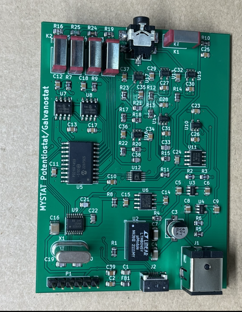
Fully assembled MyStat potentiostat
The Mystat design features many important improvements on the previous design. It has a larger potential range from -11 to 11V and it supports current values up to 200 mA. It also doesn’t lose any of its low range current capabilities, still being able to measure currents in the nA range. The Mystat also allows for easy connection of electrodes using a “headphone jack type” adapter and uses an external 15V power supply instead of relying on the computer’s USB supply for all its energy needs.
I used PCBWay for the fabrication and assembly of the device and decided to create a shared project so that anyone interested can have their own manufactured. You can use that link to buy your own fully assembled potentiostat. The total cost for the potentiostat was around 330 USD, including the power supply and cables that need to be bought separately (links for that are included in the shared project description).
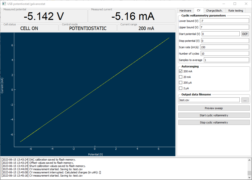
Above you can see the cyclic voltammetry of a 1K ohm resistance using the new MyStat potentiostat.
The best thing is that the potentiostat uses the exact same python software as my old potentiostat, so I was able to use a lot of the coding modifications I had done to improve my battery characterization. You can obtain my updated code here, which allows you to do battery cycling experiments charging to a final capacity or to a final potential and includes an additional display for the uAh measurement in the current cycle.
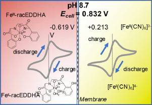
I wrote a blog post about some of my first tests of the electrochemistry of the Fe-EDDHA|Mn-EDTA system and how I planned to build a flow battery using this chemistry. I have since been able to setup a flow battery and perform some initial experiments. So far, there are several fundamental problems with the above chemistry that strongly affects its viability. I will discuss these problems below.
Fe-EDDHA solubility and pH. The Fe-EDDHA is more soluble at more basic pH values and its solubility at neutral pH is limited to perhaps only 0.1-0.2M. Furthermore, there are several less soluble impurities present – different isomers of the EDDHA – which have to be filtered before the cell is operated. Additionally, the pH changes substantially upon charge/discharge, which causes problems with the Mn-EDTA side (you’ll see later on).
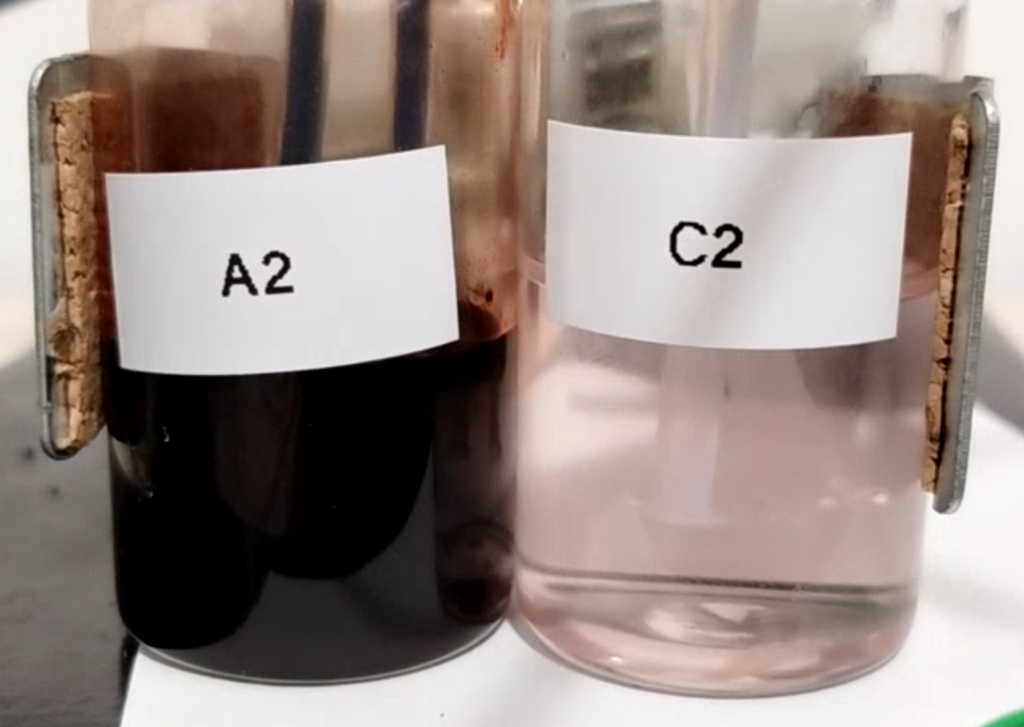
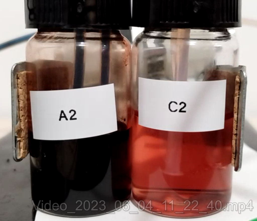
Fe-EDDHA anolyte (A2) next to Mn-EDTA catholyte (C2) solutions, both at around 0.2M.
Difficulty in working with Fe-EDDHA solutions. The solutions of Fe-EDDHA are very deeply red, basically black at the concentrations we’re working with here. This means that it is very hard to tell if there are any insoluble substances in the solution. It is also hard to tell the charge state of the solution, as it will only slowly become more transparent as the Fe-EDDHA is reduced to its Fe(II) form.
Fe(II)-EDDHA sensibility to oxygen. Once the Fe-EDDHA is reduced in the anode, the liquid becomes incredibly sensitive to any oxygen dissolved in the solution, which will quickly oxidize the Fe(II)-EDDHA back to Fe(III)-EDDHA. Given that I currently have no means of purging my system of oxygen, this makes it impossible for me to run flow batteries using Fe-EDDHA right now in a reliable way.
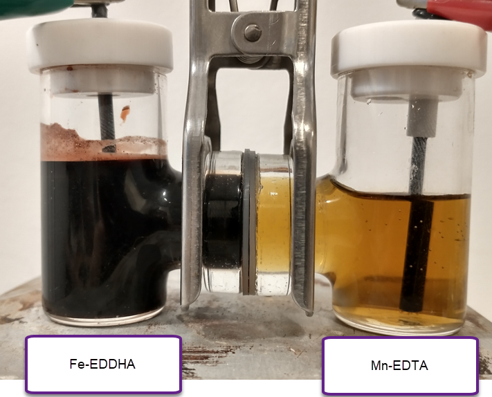
Anolyte and catholyte of the system. You can observe the red color of Mn(III)-EDTA appear in the catholyte (C2) as the flow battery is charged.
Mn-EDTA stability at higher pH. The oxidized form of Mn-EDTA, which is Mn(III)-EDTA, is red at a pH below 6.5 and yellow at a pH above 6.5 (you can see that yellow in a previous post). However, the yellow molecule is extremely unstable, therefore it is very important for pH to remain below 6.5. However, at a pH below 6.5 the solubility of the Fe-EDDHA drops substantially. The differences in pH between charge and discharge means that both systems are virtually incompatible, because as the Fe-EDDHA charges it induces changes of pH that very negatively affect the decomposition of the Mn-EDTA catholyte.
For all the above reasons, I decided I no longer will explore the Fe-EDDHA|Mn-EDTA system, as I currently don’t have the technical setup that is necessary to properly study it. Furthermore, the low solubility, difficulty of working with the Fe-EDDHA solutions and the problems with pH, make this system more complicated than I was hoping for, especially in a system I hoped to be simple for DIY.
I will continue to study flow batteries based on Mn chemistries, including Mn-EDTA (as these are very interesting), but I will likely change the anolyte to something that is more aligned with my current setup. Most likely I will have to compromise and use a potentially higher density, low cost anolyte, that will involve plating a metal on the carbon felt anode, like Zn. Hopefully in this manner I’ll be able to find a low cost setup to bring a DIY solution with a capacity at least in the 10-20Ah/L range.
I have recently been working on a project to create a DIY flow battery using Fe/Mn salts. The idea is to be able to achieve a close to or neutral pH system, with low cost salts, high concentrations of active species and good cycling ability. In today’s post I will describe some of my very preliminary results using a split cell system.
The image below shows you the experimental setup I am using. Both the right and left side contain graphite rod electrodes. The two chambers are separated by the DIY high permselectivity membrane I prepared using PVA/citric acid/phosphoric acid. The chamber on the left contains a solution of NaFeEDDHA from a commercial fertilizer source at a concentration of 0.05m + 3.5m of NaCl, while the cell on the right contains a solution with 0.05m of Na2MnEDTA + 3.5m NaCl. The pH was set to 7 using potassium carbonate (only a few milligrams were needed). Both chambers are stirred using magnetic stirring bars (tiny ones at 2mm).
A picture of the Fe-EDDHA|Mn-EDTA system. The left side has the Fe and the right side has the Mn. Both solutions are prepared at 0.05m concentration with 3m NaCl. The pH of the system is 7. System is showed after 2mAh of charge.
The idea of these first experiments at low concentration was to put some charge into the system to observe if there was any precipitation of Mn oxides on the cathode, or any other noticeable side reactions. We can also determine if there is any self-discharge due to crossing of Fe-EDDHA over the membrane by seeing the color change on the Mn-EDTA side and tracking the potential. I also wanted to observe what the potential was after charging (predicted standard potential is around 1.2V).
It is worth noting that the separation between the electrodes is quite large and the electrode area is low, so there are expected to be very substantial ohmic losses in this type of configuration. This means it is not useful for charge/discharge cycle data. However we should be able to get some important information about the reversibility of the chemistry and the presence of any bad side reactions, as mentioned above.
The capacity of the system at this (15mL per side) configuration would be 20.1mAh. I charged it to 2mAh at 2.3V, which was able to introduce current at a rate between 700-800mA. After stopping the charging process, the potential dropped to around 1.1V fast and then very slowly from that point. It will take more charge for the potential to hold steady there, but this already shows the chemistry is working. Changing the electrodes for new graphite rods had the potential still holding at similar values, which means the potential is not due to any deposits on the graphite electrodes.
Despite the big charging over-potential – due to ohmic losses – there was no depositing of metallic Fe on the anode or the evolution of any hydrogen gas (no bubbling was observed). I also could not observe the formation of any MnO2 precipitate on the cathode. This therefore means that the Mn3+ is stable, at least in the short term, in the catholyte (as expected from literature experienced with Mn-EDTA).
During the past couple of weeks I have been working on cation exchange membranes using PVA/cellulose (see here, here, here). The idea is to create a membrane that can replace Nafion in a pH neutral flow battery built using an Fe anolyte and a Mn based catholyte. In this post I will share the first results that are up to par with those of a Nafion membrane.
My initial idea was to both crosslink and add anionic sites to the PVA by using phosphoric acid with urea as a catalyst, heating the membrane to >150C in order to perform the esterification process. This worked to a decent degree, achieving membranes with permselectivity values above 80% with sheet resistance values around 10x those of Nafion membranes.
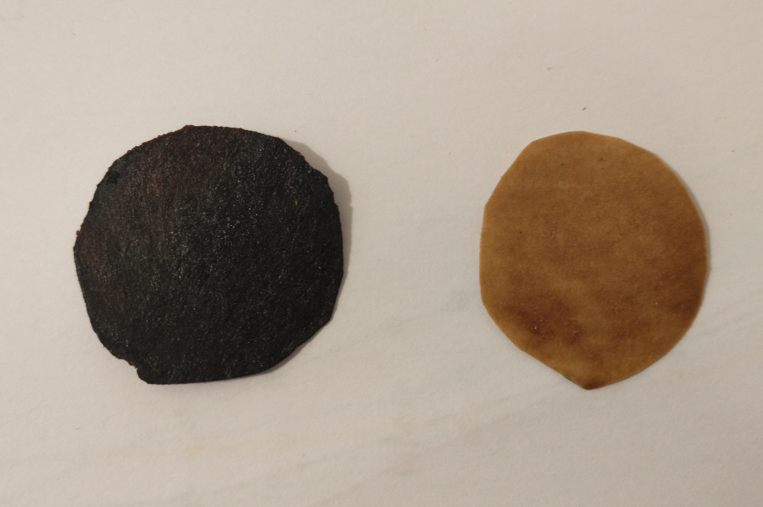
Membranes annealed at 150C (left) and 100C (right)
However there were some obvious issues with this process. The first is that the membranes produced had some stability issues, their permselectivity would drop with time – due to lack of enough crosslinking – and the mechanical stability of the membranes also left a lot to be desired. Both of these issues were likely due to limited crosslinking of the membranes, as forming a double phosphoric acid ester is not a very favorable process, even in the presence of urea.
I would see Fe-EDDHA-1 leak across the membrane within around 24 hours of setting up my cells, with the transparent side turning a slight pink within that timeframe. The permselectivity would also drop from 80% to around 40% within that timeframe. It was obvious that these membranes had components that were still dissolving or at least creating cavities that allowed too much water to flow through.
Thinking about this, I searched for possible crosslinking agents to enhance the issue. I also wanted to avoid usage of anything toxic, like glutaraldehyde, as the space where I carry out these experiments has limited ventilation, plus I want to avoid exposing myself or my cats to harmful substances. Expensive substances were also out of the question, like sulfosuccinic acid.
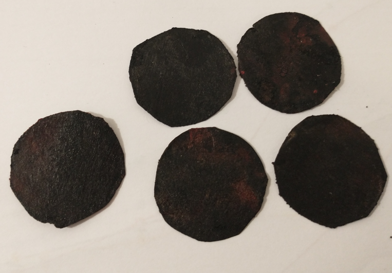
Multiple results of membranes being prepared using this method (each one is around the diameter of a 25c US coin)
Reviewing papers on the subject, citric acid appeared to be a viable substance. It is a tricarboxylic acid, so it would be able to crosslink cellulose with PVA, PVA or cellulose with themselves and also keep some exposed anionic carboxylic groups to provide cation exchange capacity. Adding phosphoric acid would also catalyze the esterification reaction plus also provide some phosphorylated sites for enhanced permselectivity.
The process for preparing these membranes is as follows:
Prepare a solution by adding 15g of PVA to 200mL of water (solution A).
Place solution A in a fridge for 48 hours, with occasional stirring/shaking. Surprisingly, cold conditions are much better for dissolving PVA because they discourage agglomeration.
Wait till solution A is fully homogeneous, keep longer in fridge and shake/stir as needed.
Prepare another solution by using 0.5mL of phosphoric acid (81%), 0.5g of citric acid and 15mL of solution A. This solution is stirred until everything is completely homogeneous (solution B).
Dip a filter paper in Solution B. I used Stony Lab 101 but other fine grain filter papers should work just as well. Make sure all excess has dripped off and tap with paper towels to remove any excess.
Place on a hot plate at 80C for 3min
Flip it to the other side for another 3 minute.
Use a brush to paint solution B on the filter paper while on the hot place.
Wait for 3 minutes.
Flip the filter paper and paint the other side, wait another 3 minutes.
Repeat steps 8-10 three times.
Increase the temperature to 150C.
Flip the membrane every 10 minutes for one hour or until the membranes appear fully black. Put a petri dish on top if needed to keep the membrane flat.
Allow the membrane to cool to room temperature.
Place the membrane in a solution with 10g/L of potassium or sodium carbonate to neutralize any remaining acid, they can be stored in a 0.5M NaCl solution.
The membranes that result from this process are black in nature. However they do not feel like charcoal and do not crumb easily. Instead, they have the feeling of a piece of plastic film, which is exactly what we are looking for. Several papers discussing citric acid crosslinking of different polymers do have resulting black films, so this isn’t necessarily a bad thing.
I was also very pleasantly surprised by the permselectivity measurement for these membranes. Measuring the potential across NaCl 0.1M | NaCl 0.5M using identical Ag/AgCl reference electrodes, the potential is 38-39mV, meaning that these membranes have permselectivity values >99%, which is equivalent to that of the best Nafion membranes. Adding 0.01g of NaFeEDDHA to the NaCl 0.5M side – which makes it dark red – I could see absolutely no crossover of FeEDDHA-1 to the other side of the half-cell experiment within 48 hours of testing. There were also no drops in the permselectivity which remains extremely high. The sheet resistance measurements are also very favorable, with in place sheet conductivity values now in the <50 ohm/cm2 range.
Overall, I am pleased with this DIY membrane result. The crosslinking of PVA using citric acid and phosphoric acid on a cellulose matrix provides you with a very robust membrane that has some wonderful characteristics. This will be my base membrane for the construction of Fe-Mn flow batteries. This membrane is also very low cost.
In a previous post I described how to create a DIY cation exchange membrane using some easy to get materials. These membranes could achieve significant permselectivity values, but still far away from those required to create membranes for a robust flow battery. Additionally, the sheet resistance of these membranes – which I measured using a 4 contact electrode method – was quite bad, with values often greater than 6000 ohm/cm2. The through plane resistance was around 3x that, although my method for through-plane resistance measurement is not reliable yet.
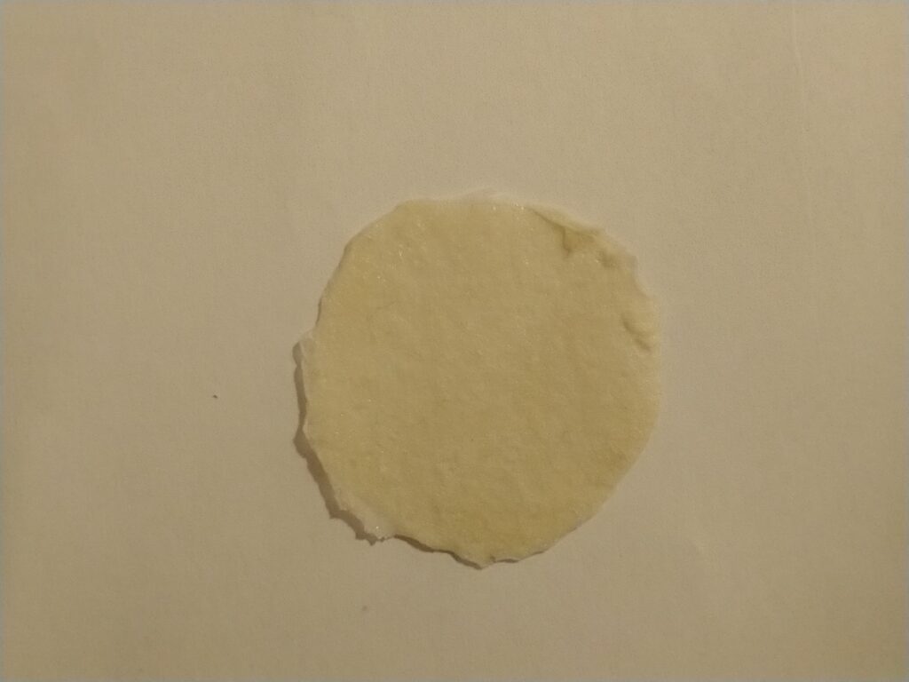
Some of the last membranes I produced using a PVA solution with a pH in the 6-7 range. The membrane remains an off-white yellowish color, but does not oxidize as in my previous tests.
In this post, I want to talk about the advancements I have made to improve the fabrication of these membranes. First of all, I have lowered the preparation temperature to 150C, this avoids charring the membranes and improves reproducibility. I also added 80 minutes of additional time at these temperature once all the PVA coats have been put on, this improves crosslinking and drastically reduces the solubility of the membrane in water (to the point where it becomes fully insoluble).
I have also found out that decreasing the acidity by adding some potassium hydroxide also helps retain membranes structure, increase permselectivty and decrease sheet resistance. This matches some papers on cellulose phosphorylation using potassium phosphate and ammonium phosphate salts, with solutions that have much higher pH values than phosphoric acid. The higher pH helps preserve the structure of the cellulose and PVA, as a lack of acid reduces the changes of degradation of the cellulose and PVA. The phosphorylation still happens, thanks to the urea catalyst present.
With this in mind, the membranes can probably be made using monopotassium or monoammonium phosphates, much more readily and less dangerous chemicals compared to concentrated phosphoric acid and potassium hydroxide.
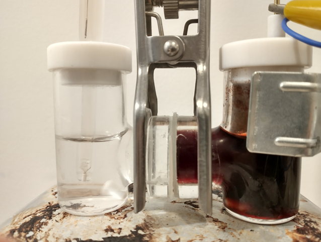
One of my last experiments to measure permselectivity. The cell to the right contains a very small amount of NaFe(EDDHA), which has a very deep red color. This makes it very easy to see membrane crossover.
The best values I have achieved so far are a permselectivity of 80% and a sheet resistance of 373 ohm/cm2. These are still much worse than those of commercially available membranes, but certainly better than the values I was achieving before.
From the parameters I have tested, the cross-linking temperature and pH seem to be the most important to the qualities of the membrane, so I will try to study these too with a bit more detail to find out if I can produce membranes with better qualities. Increasing the concentration of P at higher pH values with higher urea quantities might also help achieve better cross-linking.
In previous posts (here and here), I have talked about my goal to create an Fe/Mn flow battery and how to do this I will need to create a cation exchange membrane to use instead of Nafion. In this post I will talk about what I have achieved so far, which is the first iteration of a PVA based cation exchange membrane.
Early on, it became clear that polyvinyl alcohol (PVA) was going to be the easiest polymer choice, as it is readily available and easily to functionalize. Phosphorylation also seemed as the easiest route towards functionalization, as highly concentrated phosphoric acid is easy to get and urea catalyzed phosphorylation reactions of PVA are already well known. The introduction of phosphoric acid esters provides the ability of the membrane to repel anions and allow only cation transport.
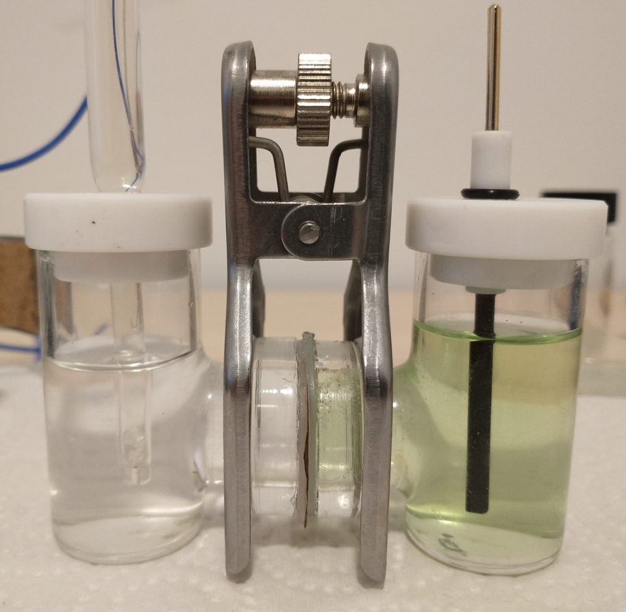
Experimental setup to measure the potential across one of the membranes created. The potential between the Ag/AgCl reference electrode and graphite electrode is measured with both electrodes on the same side, then the potential is measure again by placing the reference electrode on the opposite side. The membrane potential is calculated from the difference between same side and opposite side potentials. (a small amount of dye was added to the right side so that you can see how the membrane separates the solutions).
My first problem creating a membrane of this sort had to do with casting PVA films and being able to peel them off. These membranes are extremely sensitive and can easily stick to glass or to themselves, making the fabrication process difficult. I tried casting on glass petri dishes – with mold release – and was unable to remove them without breaking them. A friend suggested casting on Al foil instead, so I will be keeping this for a future experiment.
Furthermore, the few times I was able to successfully peel off films, the films then dissolved quite easily in water. Although I thought the phosphorylation of the PVA would provide some crosslinking, it definitely increases the solubility of the polymer in water, making things actually worse. Using things like aldehydes for crosslinking is not going to be work, but perhaps future experiments with boric acid or citric acid would help with this issue.
A breakthrough came when I realized that cellulose is also known to be phosphorylated with phosphoric acid plus urea and that it could therefore be cross-linked through a phosphoric acid ester with PVA. The cellulose could also provide a support, which would greatly enhance my ability to work with the PVA solids.
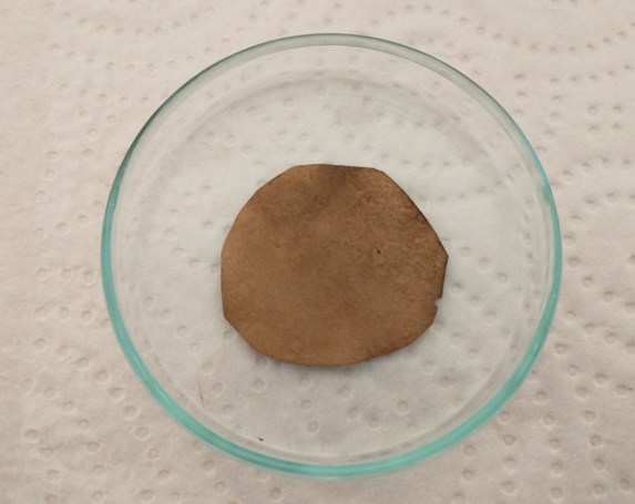
Final result of the process mentioned below
My fabrication process was as follows:
To 15mL of ice cold distilled water add 1g of PVA, 1g of Urea and 1mL of 81-85% phosphoric acid. This is solution A.
Place in a fridge for 48 hours, with occasional stirring/shaking. Surprisingly, cold conditions are much better for dissolving PVA because they discourage agglomeration.
Wait till solution A is fully homogeneous, keep longer in fridge and shake/stir as needed.
Dip a filter paper in Solution A. I used Stony Lab 101 but other fine grain filter papers should work just as well. Make sure all excess has dripped off and tap with paper towels to remove any excess.
Place on a hot plate at 180C for 3min
Flip it to the other side for another 3 minute.
Repeat steps 4-6 once.
Place on the hot plate with a petri dish on top (to keep it flat) for 1 hour.
The result should be as shown in the image above.
The process seems to work. The resulting membrane is not soluble in water, is sturdy and easy to manipulate and loses the micro porosity of the filter paper. It is quite brown, which means some oxidation has happened, but reducing the temperature or time leads to membranes that are not properly crosslinked, and dissolve quite easily (leaving just a porous cellulose membrane behind).
To determine whether the above membrane is in fact a cation exchange membrane, I can measure its permselectivity. To do this, I measure the membrane potential between a 0.1M NaCl and a 0.5M NaCl solution (more details about this process on the first image in this post). The membranes produced in this way have permselectivity values between 0.5-0.7, which means that the membrane does in fact act as a cation exchange membrane. However, the membrane is nowhere as good as Nafion, which has a permselectivity >0.95 under these conditions.
I will now try changes in the composition of solution A and optimize the curing temperature to increase the permselectivity of the membrane. So far I think the fabrication process is quite straightforward which allows me to reproducibly fabricate the membranes described in this post.
To build an Fe/Mn flow battery we need a cation exchange membrane to separate the catholyte and anolyte chambers of the device. In this post I want to talk about my initial thoughts about how to create a DIY membrane for this purpose.
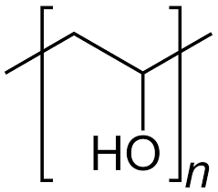
Chemical representation of PVA (Polyvinyl alcohol) not to be confused with polyvinyl acetate (what PVA glue is made of).
Commercial cation exchange membranes do exist. Nafion membranes are the most commonly used, but their cost is too high. Just a small 10cm x 10cm square of Nafion can cost upwards of 50 USD, depending on the type of Nafion used. Lower cost membranes (like SPEEK based membranes) have been tested in the literature, but I cannot find any place that actually sells these “lower cost” membranes at a truly lower cost than Nafion.
To be able to make a viable DIY flow battery we need a membrane that we can make, that is lower cost. The requirements of a cation exchange membrane for the Fe/Mn system would be as follows:
Not dissolve in water at neutral pH.
Made from readily available, low cost materials.
Mechanically stable.
No reaction with any of the redox species in solution.
Contain anionic groups (which makes it selective to cations)
Have high conductivity
I looked at potential materials to build this membrane and PVA has become the most prominent base material. It is a polymer with OH functional groups, which I can use to react with readily available chemicals to create a functionalized polymer. My first experiments will involve using phosphoric acid, urea and potassium silicate to create functionalized membranes.
I will prepare 10% w/w solutions of PVA in distilled water, then add different amounts of the above mentioned additives to determine which compositions cast best and have the best properties. I will be casting the films in petri dishes, as this seems to be the most common method in the PVA membrane literature. I will also possibly anneal the membranes by heating them at different temperatures after they have settled.
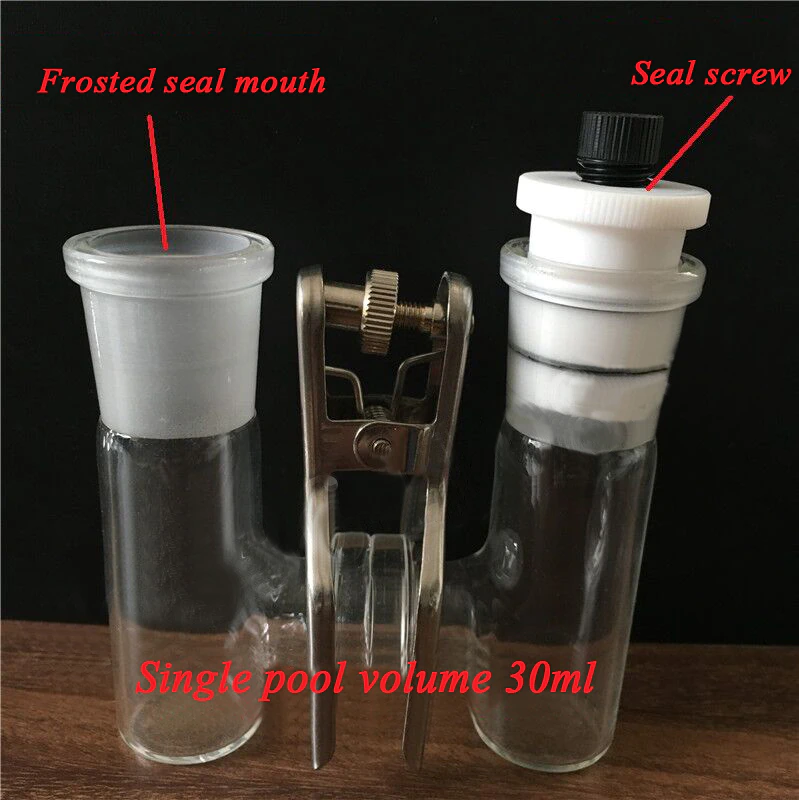
Double chamber electrochemical cell I bought (haven’t received it yet)
I have also bought a double chamber electrochemical cell to perform experiments using these membranes. The idea is to measure if there is any crossover across the membranes and possibly also measure the ionic conductivity of the membrane.
To measure crossover of ions I can setup one side with the Fe salt and another with the Mn salt, then carry out cyclic voltammetry measurements on the Mn side as a function of time, to measure the appearance of the Fe peak (if there is any crossover). I can compare times between membranes as well. I can also test microporous membranes and non-functionalized PVA membranes, to obtain some baseline measurements. If I setup one side with just NaCl and the other with Fe, I can likely obtain more sensitive measurements (as I will have no current from reactions with Mn species).
Additionally if I use Fe-EDDHA I could sample the solution and measure the appearance of the Fe-EDDHA visible absorption peak near 500nm, which is highly sensitive given the chelate’s very high molar extinction coefficient. Although for this I would near to purchase a Uv-Vis spectrometer, which would cost me 500-1000 USD.
I can also measure ion diffusion by setting up distilled water on one side and a 3M NaCl on the other side and measuring conductivity as a function of time on the distilled water side. This will allow me to compare different membranes and see which ones transport ions faster. If I add Fe chelate to the NaCl I could perhaps measure both ion transport and selectivity simultaneously.
I have previously discussed my project to create a DIY flow battery using Fe/Mn chemistry. On this post I want to expand on the potential limits of this chemistry and some modifications that should enhance our ability to increase its energy density and performance.
My first idea is to attempt to create a flow battery using an NaFe(EDTA) solution as anolyte and an Na2Mn(EDTA) solution as catholyte. This battery would have a potential of around 0.74V, as I measured by cyclic voltammetry (CV) of the species involved. I commented on how the limit of solubility of these chemicals – without any additives – is limited to at best around 0.5M, which limits the battery power density to around 10 Wh/L.
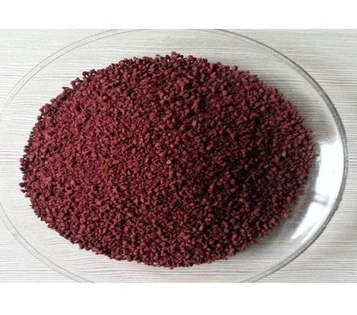
This image shows some NaFe(EDDHA)
However, it is interesting to note that the solubility of these EDTA salts increases aggressively with pH, such that both can be dissolved above 1M at a pH of 7. I confirmed that the solubility increases aggressively as a function of pH, being able to create a solution that was around 1M for both compounds with 3M NaCl supporting electrolyte. To do this I used potassium carbonate to increase the pH gradually to the 7-7.5 range. I also confirmed that the reversibility of the electrochemistry was unaffected through CV, although both standard half-cell potentials are shifted negatively by around 50mV.
This increase in solubility is interesting, as it increases the power density of the battery substantially. If the compounds can be dissolved at 2M, then it would give the battery a density closer to lead acid, at 40Wh/L.
Sadly there are no published studies that show the solubility of EDTA salts as a function of pH, however one of the few published studies of Mn-EDTA in flow batteries (here) shows that you can dissolve Na2MnEDTA at concentrations past 1M. I have bought some additional Mn-EDTA to perform my own solubility experiments, I will let you know what I find out.
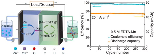
Image from this study, using a Zn/Mn flow battery at slightly acidic pH.
Image from this study using Fe-EDDHA at a slightly basic pH.
Another interesting note is to look at other Fe chelate candidates. While EDTA is the lowest cost chelate, the Fe-EDDHA chelate is interesting, as it has a significantly more negative potential Vs Ag/AgCl (-0.6V instead of -0.1V for Fe-EDTA). Recent literature of Fe-EDDHA chelate characterization and its use in flow batteries already shows its practical application (here and here). This increases the potential of an Fe/Mn battery from 0.74V to around 1.2V, which is a decent potential to achieve within the stable window of water at pH 7.
This means that, if using Fe-EDDHA, we could potentially achieve a power density of up to 80Wh/L at a solubility of 2M. If the solubility limit is around 1M, then it should still allow us to get to 40 Wh/L. With this in mind, the Fe/Mn chemistry should match lead acid power density and be a strong competitor against Vanadium based chemistries. This is especially given the fact that Fe/Mn are super abundant and this battery is based on already commercially available chemicals in water, at a neutral pH.
As you can see above, the anolyte and catholyte I propose have been tested, so this is definitely a system that can be built in a rather straightforward manner.
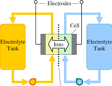
Flow batteries are a great approach for large scale energy storage. While in a battery the amount of energy is constrained by the mass of the anode and the cathode, in a flow battery the cathode and anode are stable electrodes (most commonly graphitic foams) and the energy is stored in solutions that are pumped through these electrodes.
General diagram of a flow battery.
Many of the lowest cost approaches to the chemistry of a flow battery are unable to fully take advantage of this, because they reduce a metal to its solid form on the anode. Approaches using Fe and Zn where this happens are common. The deposition of a solid metal then creates additional issues with both passivation and with dendrites, which can end up shorting the flow battery down the line.
To solve these issues, we need a chemistry where both the oxidation and the reduction happen in solution (with no solid formation on the electrodes). Additionally both of the half-reactions need to be reversible. From a DIY perspective, they should ideally happen under mild conditions and, to make things even more difficult, we need materials that are low cost and that can be easily purchased.
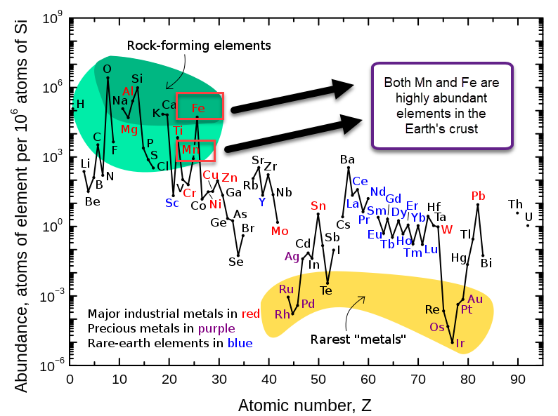
Relative abundance of elements in the earth’s crust
Manganese (Mn) and Iron (Fe) are some of the most common elements on the Earth’s crust, so they fulfill the cost issue. However, when building a flow battery with Mn, we find that the oxidation reactions that Mn is involved in generally involve the formation of insoluble Mn oxides. This happens because Mn3+ is generally unstable in solution and reacts with water to create Mn2+ plus an Mn4+ oxide or hydroxide.
However, a few papers have been published on the use of Na2Mn(EDTA) in flow batteries. This chelate – a commonly available fertilizer – protects the Mn3+ from reacting with water and enhances the reversibility of the reaction. Given the potential where the oxidation of Mn(EDTA)-2 happens, I thought it could certainly be coupled with the reduction of Fe3+ to create a flow battery. Additionally NaFe(EDTA) is also a low cost highly available fertilizer we can use.
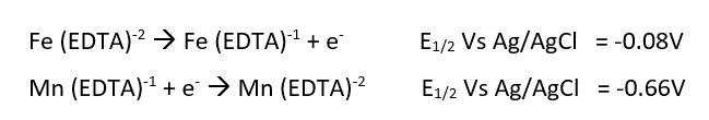
On a previous post, I spoke about a setup for electrochemistry that I created, which allows me to carry out several measurements in solution. Using cyclic voltammetry of a solution containing Na2Mn(EDTA) and NaFe(EDTA) I was able to characterize the system and obtain half reaction potential values for the Fe and Mn reactions mentioned above.
Half reactions and half reaction potentials measured Vs an Ag/AgCl reference electrode. For Mn the reduction is shown.
Cyclic voltammetry used to obtain the E1/2 measurements. The Fe reaction happens to the left while the Mn reaction happens to the right.
If we add the two potentials above, we can obtain the expected potential for our battery, which would be 0.74V. This is not very high, which means that the energy density of our flow battery system is going to be low. If we consider the solubility of both compounds, then we expect the power density of this battery to be around 10Wh/L. This means that you would need 100L of 0.5M NaFe(EDTA) and 100L of 0.5M Na2MnEDTA to get a 1kWh battery. This means 18.3kg of the Fe salt and 19.5kg of the Mn salt. You will also need around 35kg of NaCl as a supporting electrolyte.
At retail you can find both Fe and Mn salts for a price of around 6-15 USD/kg (if you buy 25-55lb bags). On the low end this means the cost would be 226.8 USD/kWh and on the high end 567 USD/kWh at a retail price point. In pallet amounts, the cost for both is around 2 USD/kg, so the cost goes down to 75.6 USD kWh. Note that this is only for the Fe and Mn salts.
The challenge is now to create a small electrochemistry setup with two electrochemical chambers separated by an ion exchange membrane where we can carry out some initial charge/discharge measurements and measure the cross-over of ions without the need to do any sort of pumping. This is also going to involve the design of some DIY low cost membranes, since Nafion membranes would be extremely expensive. Additionally, since the conditions are so mild (pH 5-6), we can use some modified PVA or cellulose cation transport membranes that can be produced for very low cost.
With my DIY potentiostat/galvanostat, I can perform many types of experiments. One of the most useful – especially for its link to battery chemistry – is the cyclic voltammetry (CV). In a CV experiment, the potential between a working and reference electrode is changed within a range and the current at each potential measured. The shape of the plot measured, gives important information about the chemistry in the solution. You can tell if anything is oxidized or reduced, at which potentials these processes happen and you can also get an idea about the reversibility of the reactions taking place.
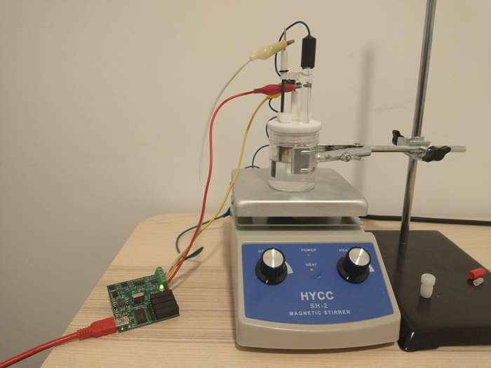
My home cyclic voltammetry setup
A CV setup has several components. The experiment is carried out in an electrochemical cell, which is a glass vessel that can hold all of the electrodes in place, without any risk of the electrodes ever touching each other and causing a short. Although such setups can be built at home, relatively low cost high quality solutions are indeed available.
The cell has a three electrode setup. The first is the working electrode (WE) which is the electrode where the relevant electrochemical processes will happen. This electrode is usually made of an inert material – glassy carbon, platinum and gold are most common – with a high polish and a limited surface area. This is because we want the surface of the electrode to be reproducible and to always provide us with the same measurements.
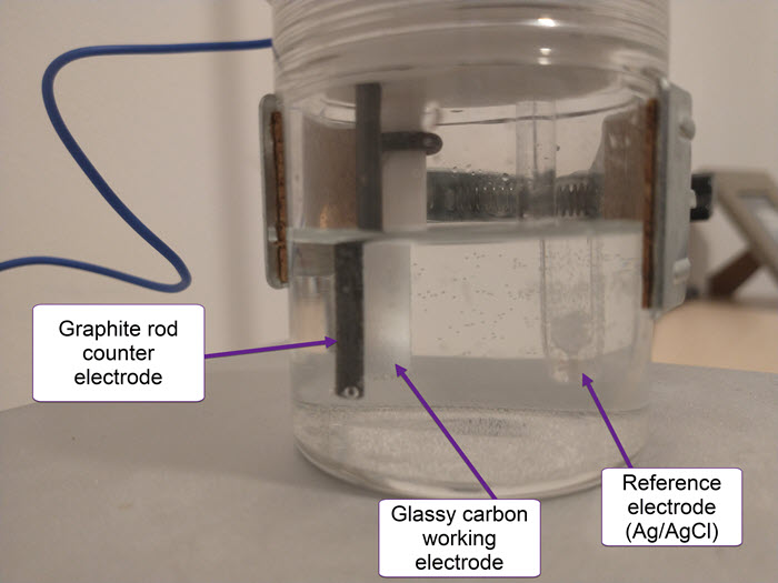
Image showing the WE, RE and CE of my home CV setup.
The reference electrode (RE) provides us with a potential based on a chemical reaction that is always happening at a very defined potential. For best results, these are usually 1 electron reactions that happen at a very small scale – which means a current draw below pico amps – and normally involve an equilibrium with an insoluble solid. Popular choices are calomel and Ag/AgCl electrodes.
Finally the counter electrode (CE) is the electrode that is connected to ground and has a polarity opposite to that of the working electrode. It is meant to complete the circuit. This is generally made of an inert material and should have a very high surface area compared with the WE, such that reactions are never limited by it. Popular material choices are graphite rods and palladium and platinum wires.
First successful CV experiment using my home setup. This was a transition metal mix (including Fe, Mn, Cu and Zn in 15% phosphoric acid). This was simply to ensure everything worked as expected.
Although the above might all sound complex and expensive – I got quotes of over 1000 EUR for the above with some EU supplier companies – I was able to find everything on ebay for relatively low prices from Chinese suppliers:
The total price for the entire setup including shipping – not counting the DIY potentiostat – was around 162 USD. I am very satisfied with the quality of all the components that I have received. I have also successfully performed my first CV experiment (showed above).
My first idea with this CV setup is to explore manganese chemistry and measure the reversibility of Mn2+ oxidation reactions in concentrated sulfuric acid solutions. Highly reversible Mn+2/M+3 reactions are very important for Mn based flow batteries.
I’ve done a lot of experiments during the last two years around the construction of Zinc halide batteries, in particular, Zn-Br and Zn-I batteries. So far, I have been unable to find a battery setup that provides high energy and coulombic efficiencies, high capacity and high stability.
Zinc-Bromine batteries suffers from problems related with Br2 diffusion, zinc dendrites, hydrogen evolution and other problems that arise when you try to resolve these issues. Trying to add complexing agents, increase electrode distance or add physical barriers, will often increase coulombic efficiency at the expense of energy efficiency, such that batteries with low self-discharge or high capacity will tend to have extremely low energy efficiency values (often below 20%). Having a battery where you need to put 20kWh in to take 2kWh out is just not a viable strategy for most people. Hydrogen evolution reactions are also inevitable with Zn-Br batteries, and these irreversibly destroy the electrolyte as a function of time.
Zn-Br batteries might be easy to show in online videos and tout as a great chemistry with lots of possibilities, but the reality of constructing a >60Wh/L static Zn-Br battery with a long cycle life shows that this is extremely hard to achieve. This is why you will find no one showing proper testing – charge/discharge curves with CE and EE numbers for many cycles – of such DIY static batteries. You can read other posts in my blog and this forum thread, for more information about my journey in Zn-Br batteries.
The above were the reasons why – after doing a lot of experiments to get to know these batteries quantitatively – I decided to move to the Zinc-Iodine chemistry.
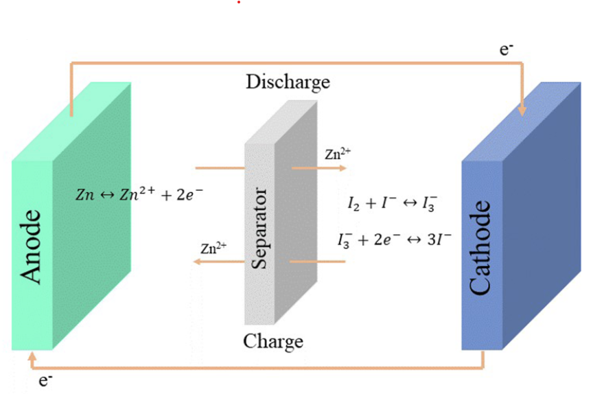
Image showing the reactions in a Zinc-Iodine battery. Note that in a static battery, the separator transports all ions, not only Zn2+ ions. This image was taken from here.
Zinc-Iodine batteries do not suffer from hydrogen evolution issues – due to the lower potential needed to charge the battery – but they also have strong problems dealing with I2 migration, especially due to the very iodide rich electrolyte, which generated a lot of readily soluble triiodide (I3–). Although many solutions to these problems have been tried and published in peer reviewed journals, most are extremely hard to apply in practice and out of reach for someone with limited equipment and resources.
However, there is some hope. A paper published in 2019 got around the problem of the triiodide ion by using a “water in salt” approach (WiS). That is, they create a very highly concentrated solution of zinc chloride and potassium iodide, where water is a very minor component by mass. In this case, they add around 2g of ZnCl2 and 0.8g of KI to only 1mL of distilled water. In such a concentrated salt solution, iodide prefers to bond to Zn to form complexes, as the formation of the triiodide ions is strongly disfavored by the environment. This is proven extensively in the paper by the use of Raman spectroscopy, supported by computational chemistry calculations.
Thankfully, both ZnCl2 and KI are readily available chemicals plus, the electrode and separator material used by the researchers are also easy to get. The cathode is made out of carbon paper, the anode is zinc metal and the separator is cellulose filter paper. I purchased the salts for around 4 USD/kg (ZnCl2) and 40 USD/kg (KI).
Note that ZnCl2 is extremely hygroscopic, so it needs to be kept under airtight conditions. Solutions of ZnCl2 are also extremely acidic (pH < 1) so you need to be very careful when handling ZnCl2 solutions that are this concentrated. Zinc chloride also heats solutions aggressively when dissolved.
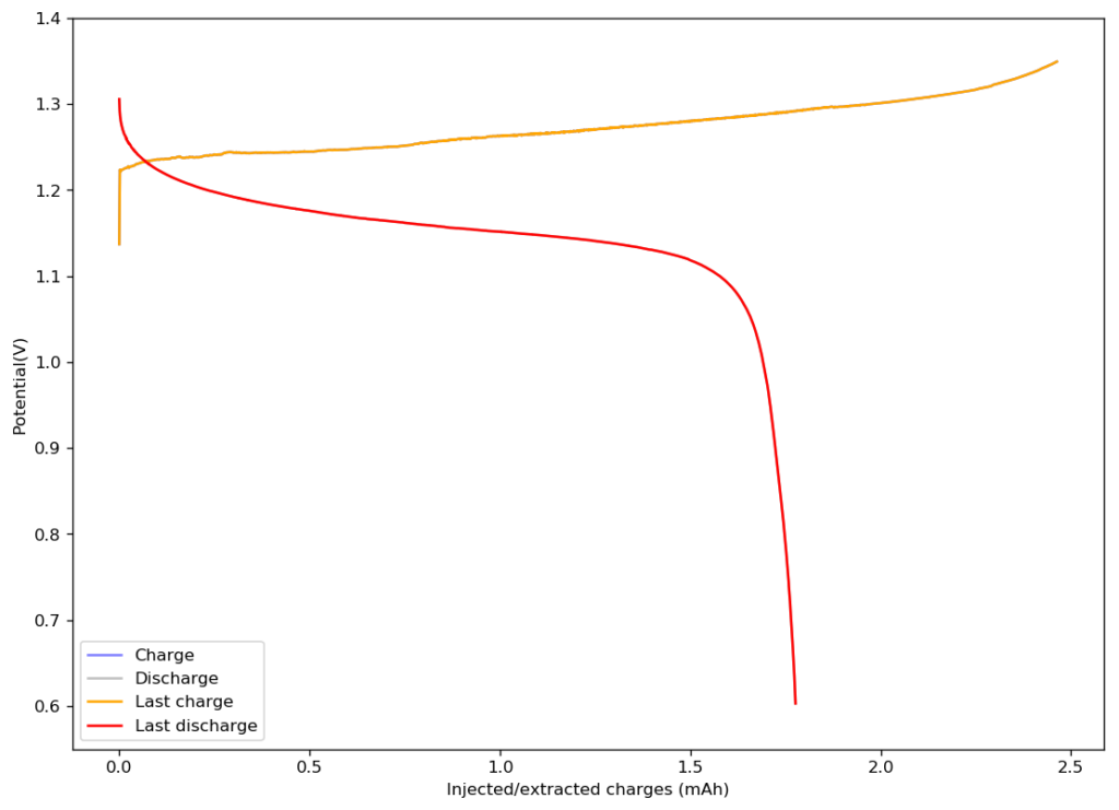
The results of trying to reproduce their research were quite astonishing. I prepared the electrolyte as published and used my Swagelok cell for testing. I used a Whatman 42 filter paper as separator and an HCB-1071 carbon cloth as cathode (note the variety kit has the 15mil, which is the one I used). For the anode, I used the surface of the graphite electrode of my Swagelok cell. In total, the thickness of my battery was just 350 microns (0.0350cm).
First cycle of my WiS cell. The device was charged to 1.35V and discharged to 0.6V at a constant current of 5mA. The CE of this device is 72.5% with an EE of 64.69%. The device has an area of 1.29cm2 and a thickness of 0.0350cm.
The above image shows you the results from the first charge/discharge cycle of this device. The capacity in this first cycle was 1.77mAh. Given the volume of this battery, the energy density is currently at 58Wh/L, the best energy density I have been able to create for any device.
I am now going to study the cycling characteristics of these devices further. I want to determine how the CE and EE change as a function of time and how the capacity changes as well. Taking this device apart confirms that elemental iodine is deposited on the carbon cloth and no appreciable triiodide – which has an orange color – is formed. This is also confirmed by the massive jump in CE and EE in these devices.
The above chemistry finally points to a path for a DIY battery that can be easy to build with readily available chemicals and materials. My hope is that this can lead to practical capacities in the >50Wh/L, with reasonable costs and hopefully low self-discharge and a long cycle life.