Thread to keep track of our zinc-iron develepment. This is quite preliminary, based roughly off of Savinell's work.
Zinc is preferentially plated on the negative side, even though the potential for doing so is more negative than iron, which is present in solution.
SOC ranges tested have been quite minimal however.
Some of @danielfp@chemisting.com's initial testing is here:
From Daniel:
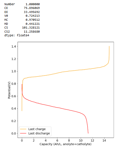
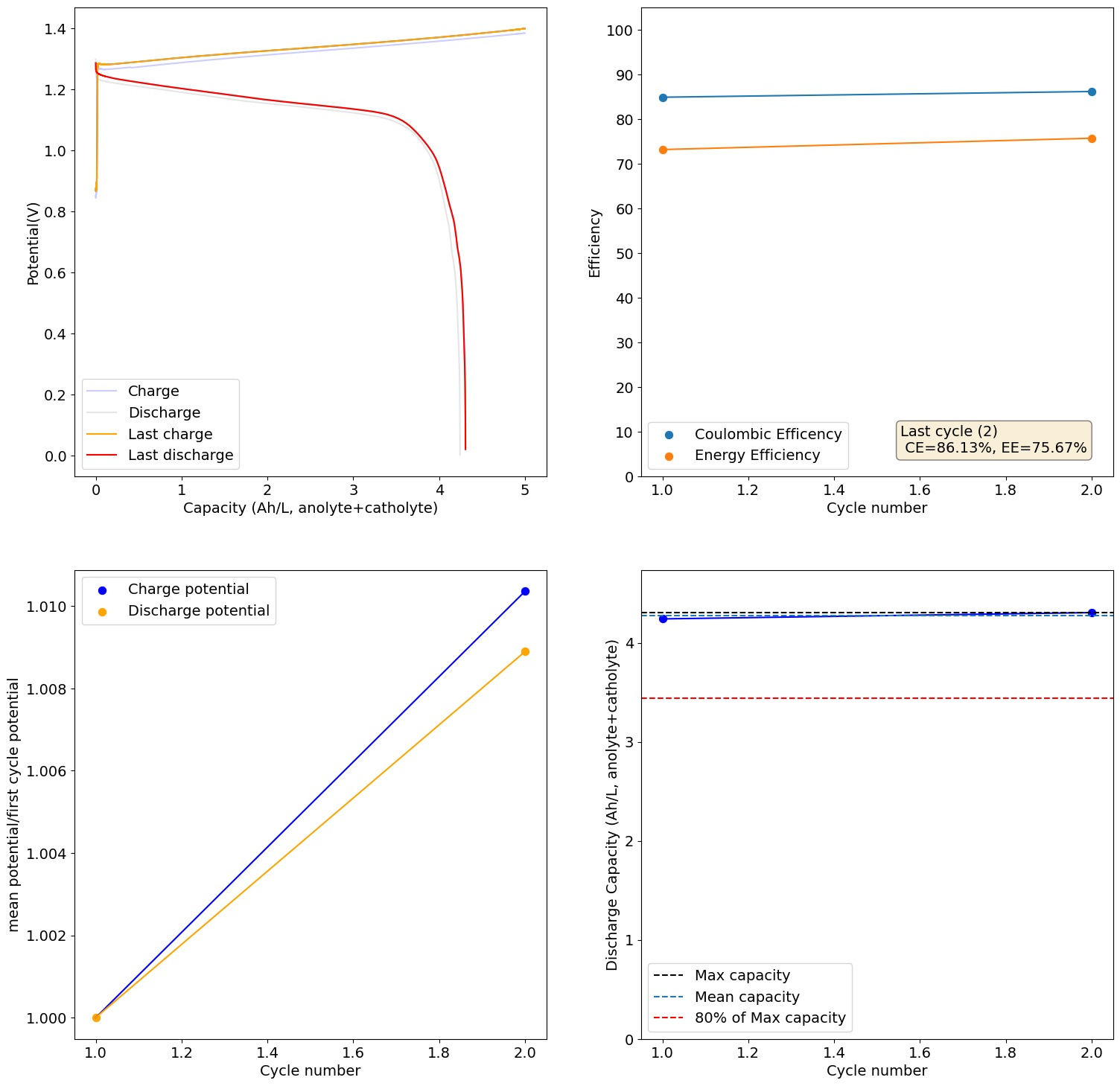
This is 2M FeCl2, 3M ZnCl2, 2M Glycine. At 20mA/cm2. Felt on both sides, daramic membrane. The pH of this is 3.2, but the CE is quite high so H2 generation must be quite low.
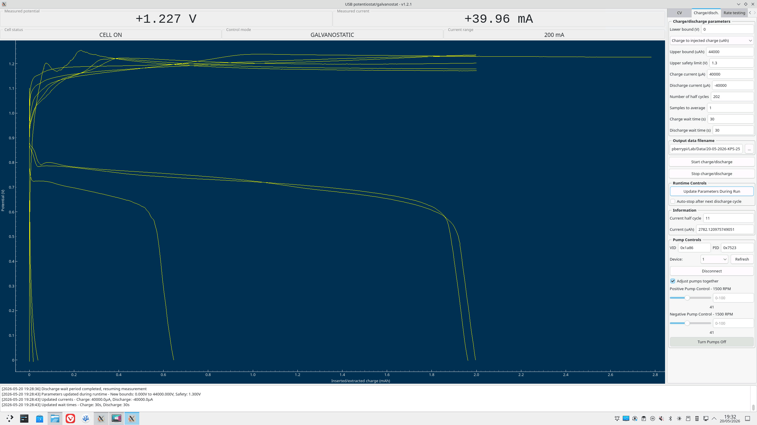
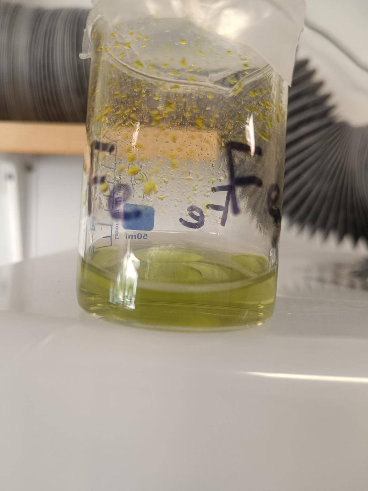
Running to higher capacities you get dendrites quite quickly. I am trying 2M FeCl2, 3M ZnCl2, 2M Glycine with 1M NH4Cl with the nonconductive felt on the anode.
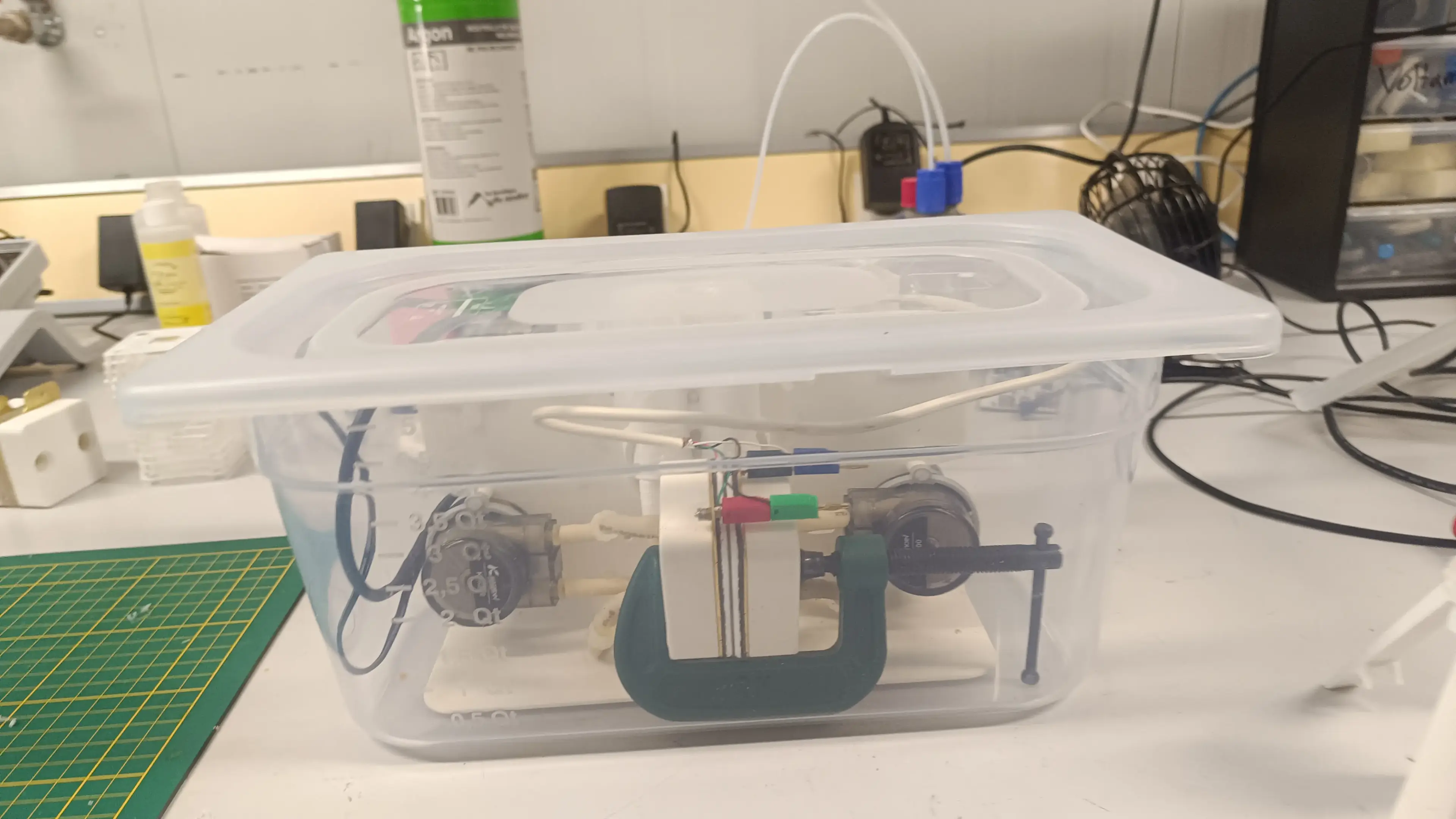
I'm also going to change to the fancy pumps with PTFE tubing after this run.