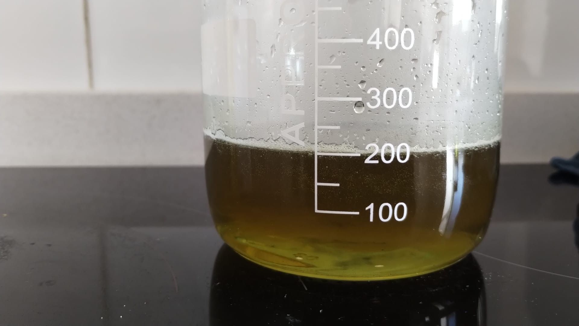
Did a few cycles at low SOC and then attempted to cycle at 10Ah/L.
Catholyte (left) anolyte (right) below:
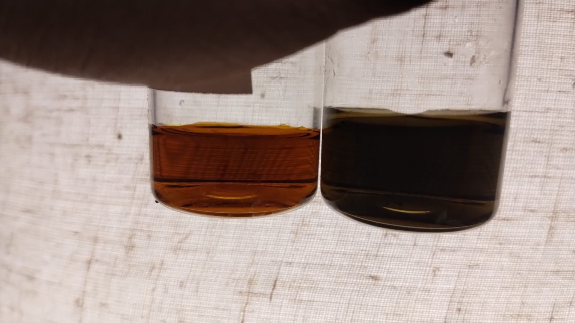
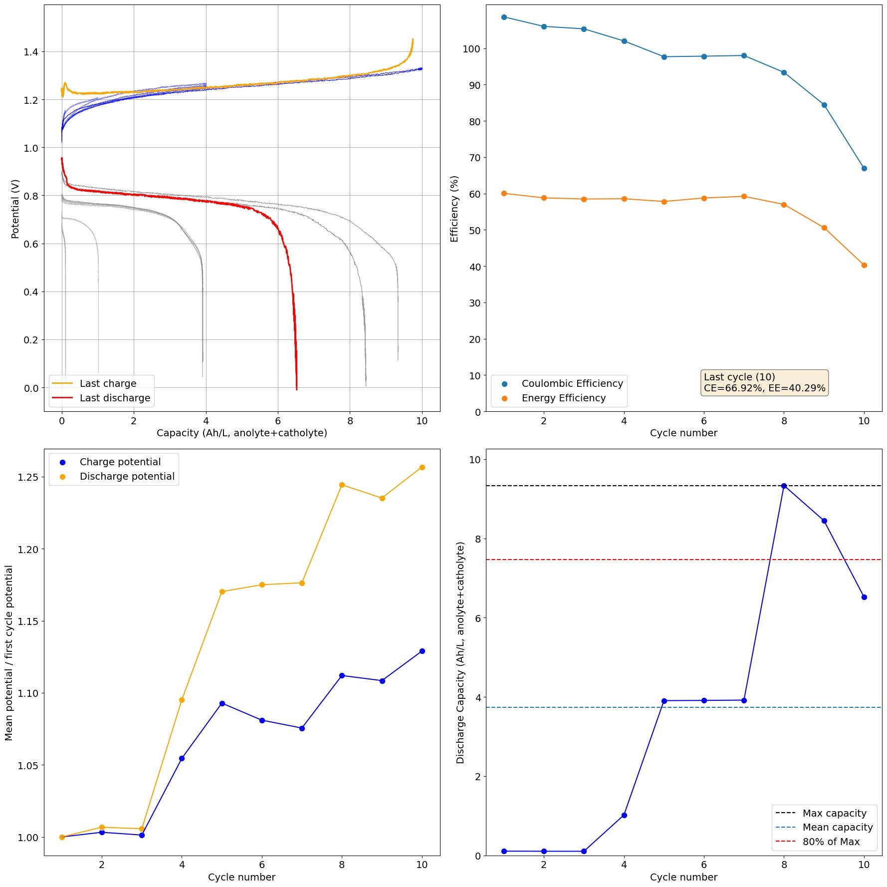
pH of catholyte was 0.24 and anolyte was 4.7. As you can see on second cycle to 10Ah/L the CE dropped from 93% to 83% and then capacity continued to decrease. On disassembly a lot of unreacted passivated iron remained on the anode, likely due to the pH increase. As Fe deposits water activity likely increases, which increases HER, which increases pH and leads to Fe passivation.
I am going to run a test adding 1M ZnCl2 to the electrolyte, to see how the additional salinity changes water activity and metal passivation.