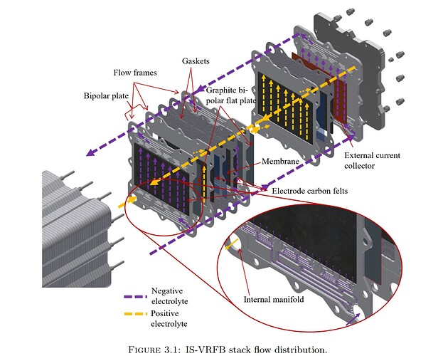
Designing the large-format cell
-
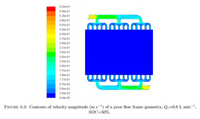
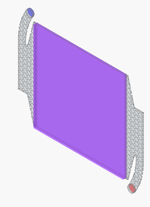
Some preliminary CFD of the simplified flow frame (U in m/s and P in Pa if I understand OpenFOAM correctly)
Conditions
- 4 L/min volumetric flowrate through one half-cell, inlet is on the top left, outlet on the lower right.
- Ambient pressure on cell outlet
- No-slip wall
- File containing CAD and CFD simulation setup is here
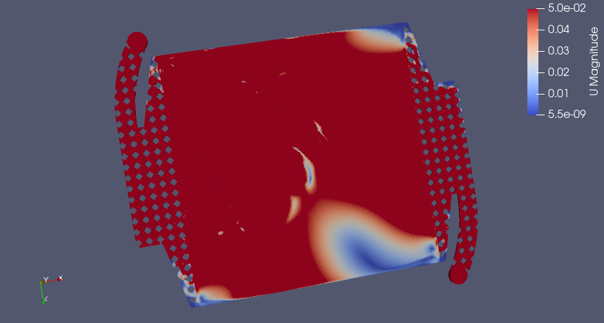
Blue is inlet, red outlet, pink is porous zone
 !
!
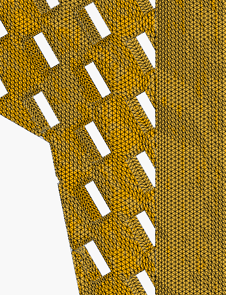
Close-up of mesh:
Flow Distribution (m/s)
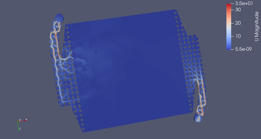
Pletcher and Walsh say a range of 0.05-0.4 m/s linear velocity is a good design range for electrolyte flow, if I apply a smaller range for velocity with 0.05 m/s as the upper limit, we see which areas in red have sufficient flow and where the dead zones are (in the corners, predictably)
Pressure Drop (Pa)

Big Caveat
Still need to calculate the Darcy-Forchheimer coefficients to do the porous zone simulation in the graphite felt, right now I am using the default values, which are almost certainly not correct. If anyone feels like finding that data (https://openfoamwiki.net/index.php/DarcyForchheimer). I think Antoni Forner-Cuenca's group has measured a lot on this recently. This could change the results quite a bit as far as flow distribution and pressure drop. I've mostly so far just been getting familiar with the simulation pipeline in FreeCAD --> CfdOF --> OpenFOAM --> ParaView.
Design is far from final, and I'm probably doing the CFD incorrectly, BUT it prints and doesn't leak! We will keep optimizing the flow frame later.
-
Hey! This is incredible work. I noticed you guys are exploring the shunt current/pressure drop/residence time distribution issue of manifold design. This is well outside my expertise, but I did run into this paper a while back from Kyle Smith, who offered a manifold design (and methodology) to resolve at least the pressure drop/residence time issue. Here's the paper - let me know if you have trouble accessing it and I'm happy to send it along.
They use a tapered header channel with straight diffuser channels and achieve very even flow rate distributions (at Reynolds numbers < 10)
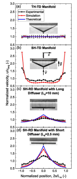
Not sure how well this prevents shunt currents but I hope this helps.
-
Hey! This is incredible work. I noticed you guys are exploring the shunt current/pressure drop/residence time distribution issue of manifold design. This is well outside my expertise, but I did run into this paper a while back from Kyle Smith, who offered a manifold design (and methodology) to resolve at least the pressure drop/residence time issue. Here's the paper - let me know if you have trouble accessing it and I'm happy to send it along.
They use a tapered header channel with straight diffuser channels and achieve very even flow rate distributions (at Reynolds numbers < 10)
Not sure how well this prevents shunt currents but I hope this helps.
@muntasirms oh this looks great, I hadn't seen the paper! It's exactly what we need for the non-shunt-current related issues (which are another bridge for us anyway, down the road). An efficient manifold seems like it could be decoupled from the shunt current protection scheme also. I will try to implement it in FreeCAD.
-
Quick video of Daniel's leak test: https://spectra.video/w/bSYUyYpJVr34N92261cd6K
-
Out of curiosity, how are you guys attaching the tubing to the cell stack? are they glued on? hose barbs? Threaded piping?
I ask because leaks are my bane in a lot of my lab setups, even with super tight bolts and threaded fittings. I'm impressed at how well you guys have managed with flexible tubing!
@muntasirms They are just barbed fittings. These have worked surprisingly well at both scales.
-
Some preliminary CFD of the simplified flow frame (U in m/s and P in Pa if I understand OpenFOAM correctly)
Conditions
- 4 L/min volumetric flowrate through one half-cell, inlet is on the top left, outlet on the lower right.
- Ambient pressure on cell outlet
- No-slip wall
- File containing CAD and CFD simulation setup is here
Blue is inlet, red outlet, pink is porous zone
!
Close-up of mesh:
Flow Distribution (m/s)
Pletcher and Walsh say a range of 0.05-0.4 m/s linear velocity is a good design range for electrolyte flow, if I apply a smaller range for velocity with 0.05 m/s as the upper limit, we see which areas in red have sufficient flow and where the dead zones are (in the corners, predictably)
Pressure Drop (Pa)
Big Caveat
Still need to calculate the Darcy-Forchheimer coefficients to do the porous zone simulation in the graphite felt, right now I am using the default values, which are almost certainly not correct. If anyone feels like finding that data (https://openfoamwiki.net/index.php/DarcyForchheimer). I think Antoni Forner-Cuenca's group has measured a lot on this recently. This could change the results quite a bit as far as flow distribution and pressure drop. I've mostly so far just been getting familiar with the simulation pipeline in FreeCAD --> CfdOF --> OpenFOAM --> ParaView.
Design is far from final, and I'm probably doing the CFD incorrectly, BUT it prints and doesn't leak! We will keep optimizing the flow frame later.
@kirk Had a few thoughts that I hope are helpful or probing at least. Disclaimer, fluids are not my strength. I'd be happy to hear more about your insights or goals here.
Colleague pointed out to me that there are correlations for different porous media geometries (e.g., see Fig 4 & Equation 2.6 and a bit more surrounding context in this paper for details https://link.springer.com/article/10.1007/s11242-020-01423-y). So if you have the permeability (and make some assumptions), you can have some bounded estimates of the coefficient.
I'm trying to digest the utility of the Forchheimer part of Darcy-Forchheimer. For a first-pass estimate of pressure drop, I'm willing to bet using Darcy's law is sufficient to approximate pressure drop (maybe the computational expense is smaller, and it's more instructive for a general audience IMO).
Regarding flow distribution: relating flow to performance I think will be challenging (there could be a lot of cell performance that is determined by other electrode complexities beyond whatever "inertial flow" does to transport of active species).
I'd also note that measuring the pressure drop directly could be relatively easy. We've done them with cheap pressure sensors such as these before: link. Maybe that could be of use and might be a way to check for inertial effects?
In any case, excited for the next steps in the modeling!
-
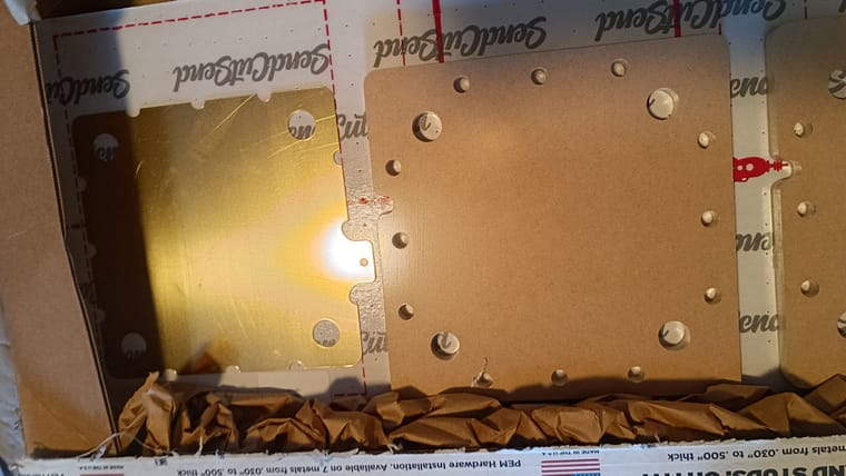
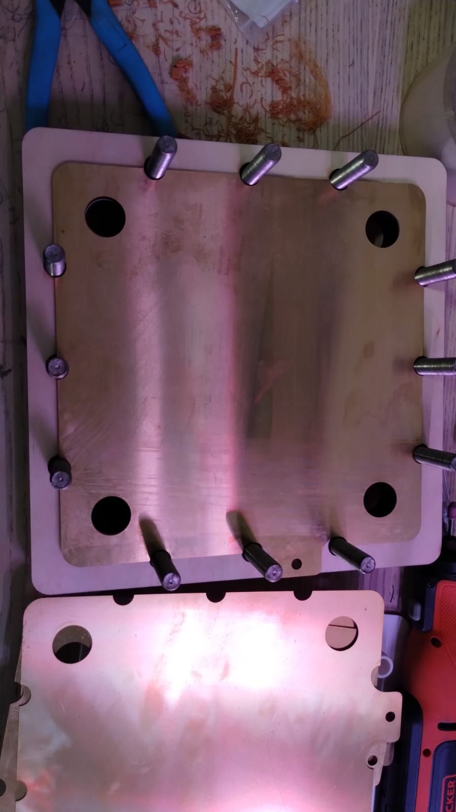
I'm finishing printing of the flowframes necessary for building the first stacked implementation. This will be a battery with three stacked cells. Each stack takes around 6mm of thickness. These are the files you have to print if you want a stacked implementation:
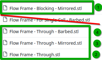
First would be blocked, then on top of that alternating through/mirrored as many times as you wish and then finally barbed at the end. For a 1kWh battery using Zn-I you would need 40 cells, so a total thickness of 24cm. I will start with a 3 cell stack, which will have a total thickness of around 2cm (counting current collectors).
-
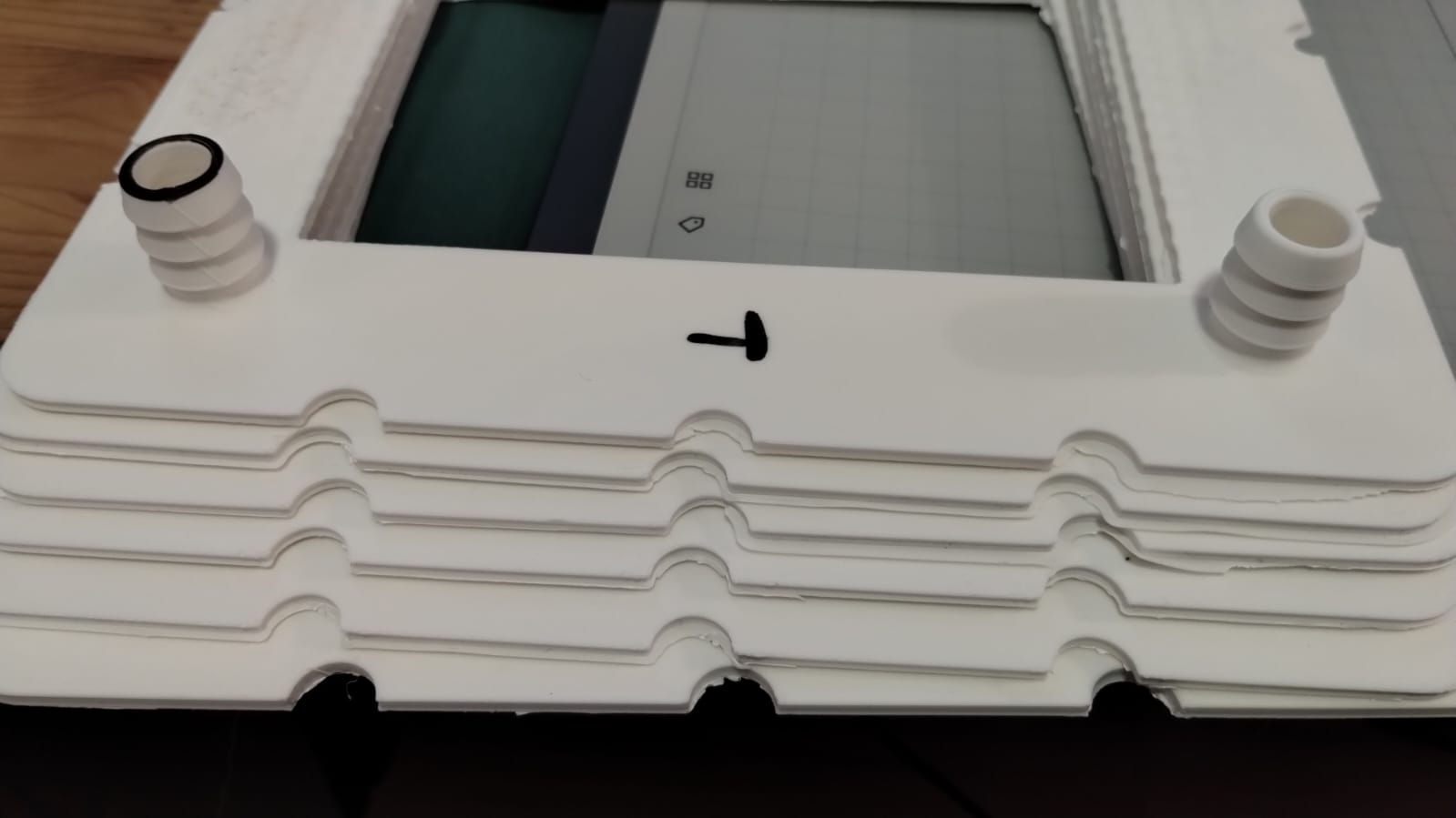
All flow frames are ready now. I'll have to wait a couple of weeks for some graphoil to cut the bipolar plate material that goes between the cells. Picture of the 6 finished flow frames below. I won't be running this with any active material, as I have no place to safely do so, I will just be testing for leaks to test the basics of the stacked design.
If ran with active material the expected voltage of this system with Zn-I would be ~3.6V and the current needed to charge it in a reasonable time would be around 3.5A. The system would produce around 12.6W, power capacity would be around 60Wh, would require around 1.5L of catholyte and 1.5L of anolyte. This would be enough capacity to run a raspberry pi for 12 hours.
-
Wow, amazing news! Especially being able to power some real world device sounds almost unreal. I guess you didn't factor in the pump consumption though.
About the safe place to run it in. Could you not just put it in a plastic container? I'm not sure if it's easy to buy large PP containers that are not IBC containers.
said in Designing the large-format cell:
About the safe place to run it in. Could you not just put it in a plastic container? I'm not sure if it's easy to buy large PP containers that are not IBC containers.
https://www.fasswulf.de/products/300-l-ibc-container-kunststoff-palette-150-50-un-zulassung
This LDPE container might work (after cutting the top off
 ) even if LDPE might not be ideal for mong term storage of triiodide.
 -
said in Designing the large-format cell:
About the safe place to run it in. Could you not just put it in a plastic container? I'm not sure if it's easy to buy large PP containers that are not IBC containers.
https://www.fasswulf.de/products/300-l-ibc-container-kunststoff-palette-150-50-un-zulassung
This LDPE container might work (after cutting the top off
) even if LDPE might not be ideal for mong term storage of triiodide.@sepi The problem is not so much finding containers that can be used, but what happens if there is any issue. If some hose unhooks or breaks or there is a leak, it is not safe to have 1L of concentrated iodine solution spilled at your house. I live in an apartment, so I'm unable to test anything that involves meaningful amounts of active material, just because it's unsafe to do so as leaks would put me and my family's health at risk. To test a prototype like this - with a lot of potential for leaks and problems at high volumes - I would require a safe working space where leaks can be handled appropriately and without contaminating areas I am in contact with on a daily basis.
-
Don't know what you have there, but Target, Walmart, Home Depot, or even order from Amazon, Plastic storage bins. Just set the whole project in one. They come in clear so you can see in if there is a problem without removing the lid. If it spills, the fluid stays in the bin.
-
Don't know what you have there, but Target, Walmart, Home Depot, or even order from Amazon, Plastic storage bins. Just set the whole project in one. They come in clear so you can see in if there is a problem without removing the lid. If it spills, the fluid stays in the bin.
@Vorg A spill of a container full of charged electrolyte would off gas a lot of I2, which at those amounts is a big health risk. I sadly don't have a space where I could have that happen and then be able to ventilate that safely, nor do I have a spare room I could dedicate entirely to the project. So as far as I go, I will test with just water. We will likely get a space to do active material testing safely, but probably not until sometime next year. If any of you guys can do this testing safely and feel comfortable doing so, you can also take a shot! As with our kit, all the materials for this are open source.
-
@kirk Had a few thoughts that I hope are helpful or probing at least. Disclaimer, fluids are not my strength. I'd be happy to hear more about your insights or goals here.
Colleague pointed out to me that there are correlations for different porous media geometries (e.g., see Fig 4 & Equation 2.6 and a bit more surrounding context in this paper for details https://link.springer.com/article/10.1007/s11242-020-01423-y). So if you have the permeability (and make some assumptions), you can have some bounded estimates of the coefficient.
I'm trying to digest the utility of the Forchheimer part of Darcy-Forchheimer. For a first-pass estimate of pressure drop, I'm willing to bet using Darcy's law is sufficient to approximate pressure drop (maybe the computational expense is smaller, and it's more instructive for a general audience IMO).
Regarding flow distribution: relating flow to performance I think will be challenging (there could be a lot of cell performance that is determined by other electrode complexities beyond whatever "inertial flow" does to transport of active species).
I'd also note that measuring the pressure drop directly could be relatively easy. We've done them with cheap pressure sensors such as these before: link. Maybe that could be of use and might be a way to check for inertial effects?
In any case, excited for the next steps in the modeling!
Back with an update! Getting caught up:
@quinnale said in Designing the large-format cell:
Had a few thoughts that I hope are helpful or probing at least.
Thank you, I will take a look at that reference! A pressure-drop rig may be in our future...
@sepi said in Designing the large-format cell:
Wow, amazing news! Especially being able to power some real world device sounds almost unreal. I guess you didn't factor in the pump consumption though.
Aha yes, these pumps are at least a few watts each! However, they are capable of powering much larger cells/stacks that what we have here. In an optimized system they should consume no more than a 1-2% of round-trip energy efficiency, or so I've been told. We are a ways off from that, but this would still be a big step up for us in development, and we will have to learn/solve a lot of things... it is exciting though that it's starting to approach tangible power levels!
@danielfp248 said in Designing the large-format cell:
I sadly don't have a space where I could have that happen and then be able to ventilate that safely, nor do I have a spare room I could dedicate entirely to the project.
I have a suitable location for this which is isolated and away from living spaces; I will be carrying out the first cycling tests of the large-format cell there. For reasons pointed out, although Zn-I is a relatively safe chemistry compared to say all-V or Fe/Cr, large quantities of corrosive liquid are always a risk, plus the peculiarities of iodine (which, of course, I'd rather have to deal with than say, bromine!). Zn-I is relatively accessible and well-behaved, which is why we're using it, but we'd really like to figure out some other alternatives, which we are documenting here: https://fbrc.nodebb.com/category/6/electrolyte-development.
-
I am in the process of building the test rig for the large-format cell. It will also be able to handle larger area cells, as well as stacks, and cover us for a long range of development. Just to be clear, it will be an R&D system, not something aimed at end-use! I am using conservative initial engineering design, so it will be overbuilt a tad.
The rig will be capable of:
- starting/stopping, speed controlling, and monitoring the individual power consumption of two mag-drive polypropylene centrifugal pumps (designed for use in chemical industry, currently using 6 L/min models).
- circulating two independent fluid loops through >= 1L reservoirs and a large-format RFB cell (the one detailed already in this thread)
- Charge/discharging single cells and stacks (of at least several cells), using a DC-DC configuration for now (we will be discharging the flow cell into another DC device, like an old lead-acid battery - I have a lot of those where I'm at now). For now we will be using the OwnTech Twist for this, because it is OSHW and I know the developers, and so they have to help me debug it
")
- all the power electronics will be in a proper enclosure and DIN mounted, with an emergency stop
- temp monitoring of system: thinking of monitoring ambient, cell (somewhere on the current collectors?), the outside of each reservoir, the pumps (which have thermal protection, allegedly)
- remote monitoring of the system with a Raspberry Pi + webcam. This way we can have a leak alert as well as monitor the reservoir levels independently (it is hard to find a sensor that you can put in the tank that is chemically compatible - also, want to minimize hols in the tanks!)
- I am shoving the whole thing into secondary containment and adding a fume extraction system for safety during tests
This is a non-exhaustive list - I will keep this thread updated as I build it, and add a schematic so it's clearer.
-
Here is a rough schematic of the test bench, showing where AC, DC, information is flowing:
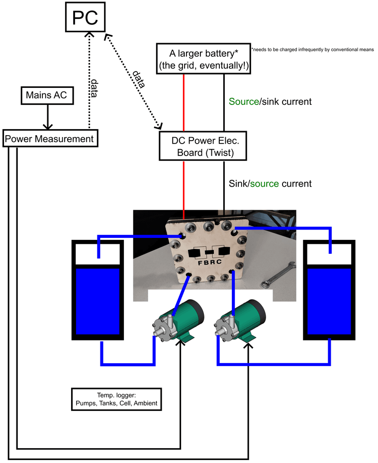
The idea of using a DC-DC converter to source and sink current into a larger battery came from the OwnTech community. Charging a battery at low voltage (1 V) and high current (>1 A) is easy, you can just use a power supply, but discharging that while measuring performance is hard; you have to have large power resistors and shunts, etc. in lieu of a proper battery cycler (which is thousands of EUR). I had originally wanted to go straight to using the Twist as a DC-AC system, sourcing and sinking from the grid, but at a single cell voltage, we are not ready to do that yet.
Why I did not put pressure or flowrate sensors in:
I tried to find flow measurement devices but could not find something affordable that was satisfactory that could be used with zinc-iodide or similar electrolytes. Acrylic rotameters or glass/metal ones could be used (along with pressure sensors) in a flow loop of pure water to test pressure drop vs. flow rate. However, this seemed like a distraction away from making our first tests with the large-format cell with the zinc-iodide chemistry. We can always measure the approximate flowrate of the pumps by dispensing water through the cell into a bucket and weighing it after a fixed time period. FWIW, these pumps are supposed to be 5-6 L/min.
Another note on flow control:
In any case, in a real flow battery in the field, I am not sure whether it is a good idea to rely on explicit flowrate measurement in the control system. Maybe a flow switch, like “is there flow or not-→ output true or false”, to avoid turning the stack on without electrolyte inside, but not a sensor giving readings in L/min or similar. Flowrate sensors that are chemically compatible are expensive and another thing that can break.
What we care about is having sufficient mass transfer of electrolyte through the graphite felt (lowers the overpotential from mass transfer, improves efficiency), but not too much flow (reduces efficiency from needless pressure drop, improvement of mass transfer by pumping yields diminishing returns). If you measure the power consumption of the pumps (easy, cheap, and robust: a shunt or current clamp), and the current/voltage data from the stack (which is already available), a properly designed control algorithm should be able to determine the ideal flowrate (or close to it), without having to know the precise value of the actual flow. Control systems engineers to the front on this one, please!
All the parts for this rig have been ordered and are in the process of arriving. After @danielfp248 finalizes leak testing (already completed at the single cell level) with his large-format cell, he is going to send it to me. I will run the initial tests with the zinc-iodide electrolyte we optimized with the dev kit.
The funding for developing the large-format cell and the test bench needed to characterize it comes from the NLnet grant we received, we are very grateful for their support!
-
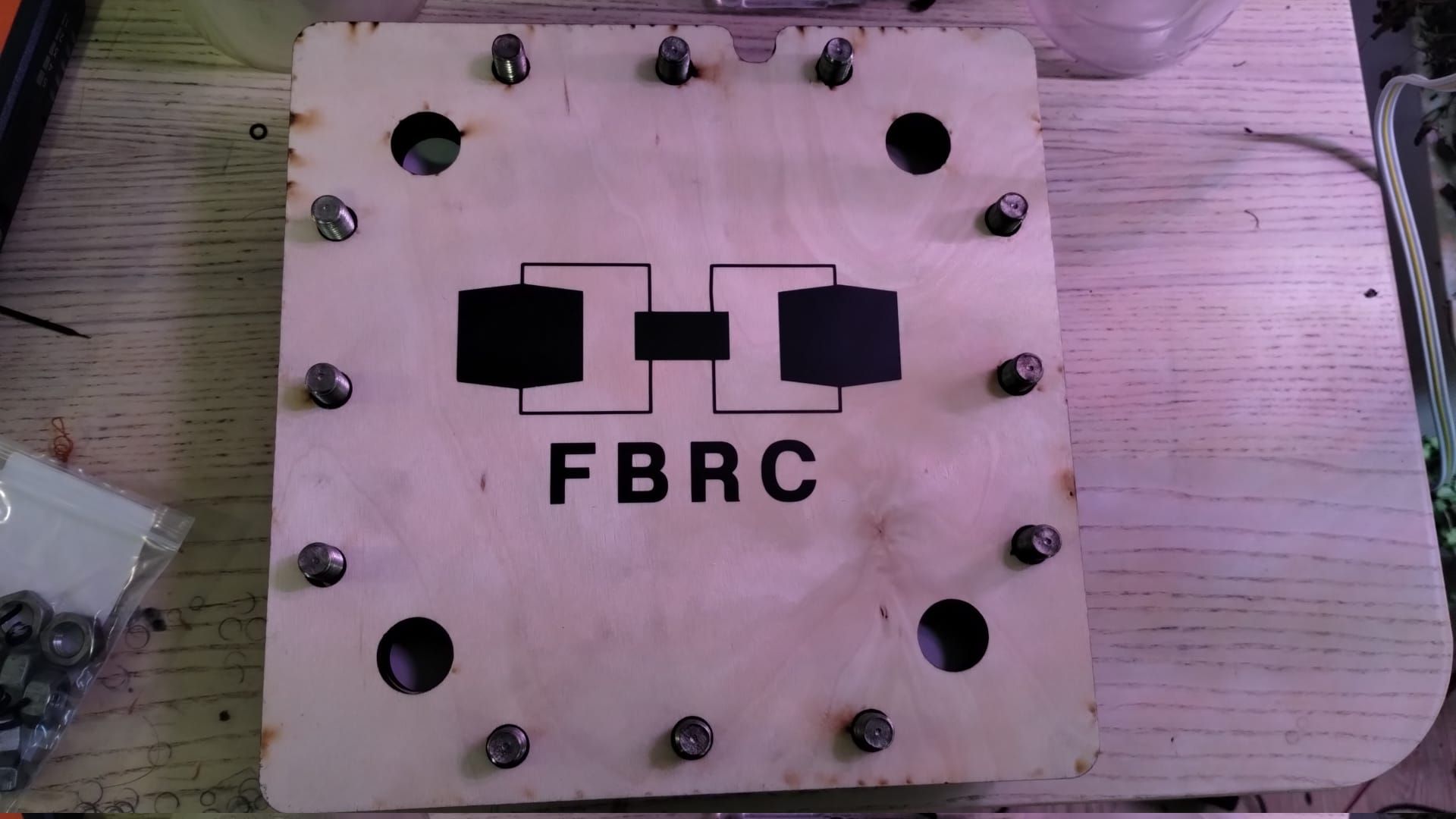
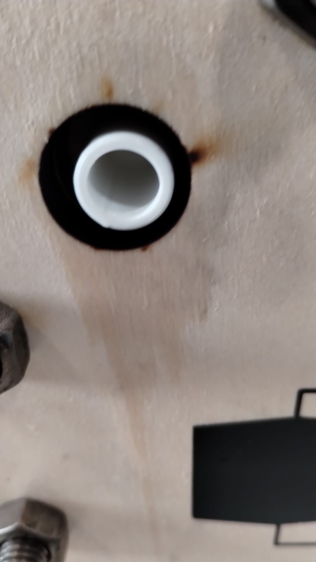
First stack assembly. This stack contains two cells. My screws weren't long enough so I had to sacrifice using one of the birch wood endplates to have it seal. Hopefully it doesn't leak!
I will keep you guys posted. I will leak test this and then mail it to kirk for testing with real electrolyte.
-
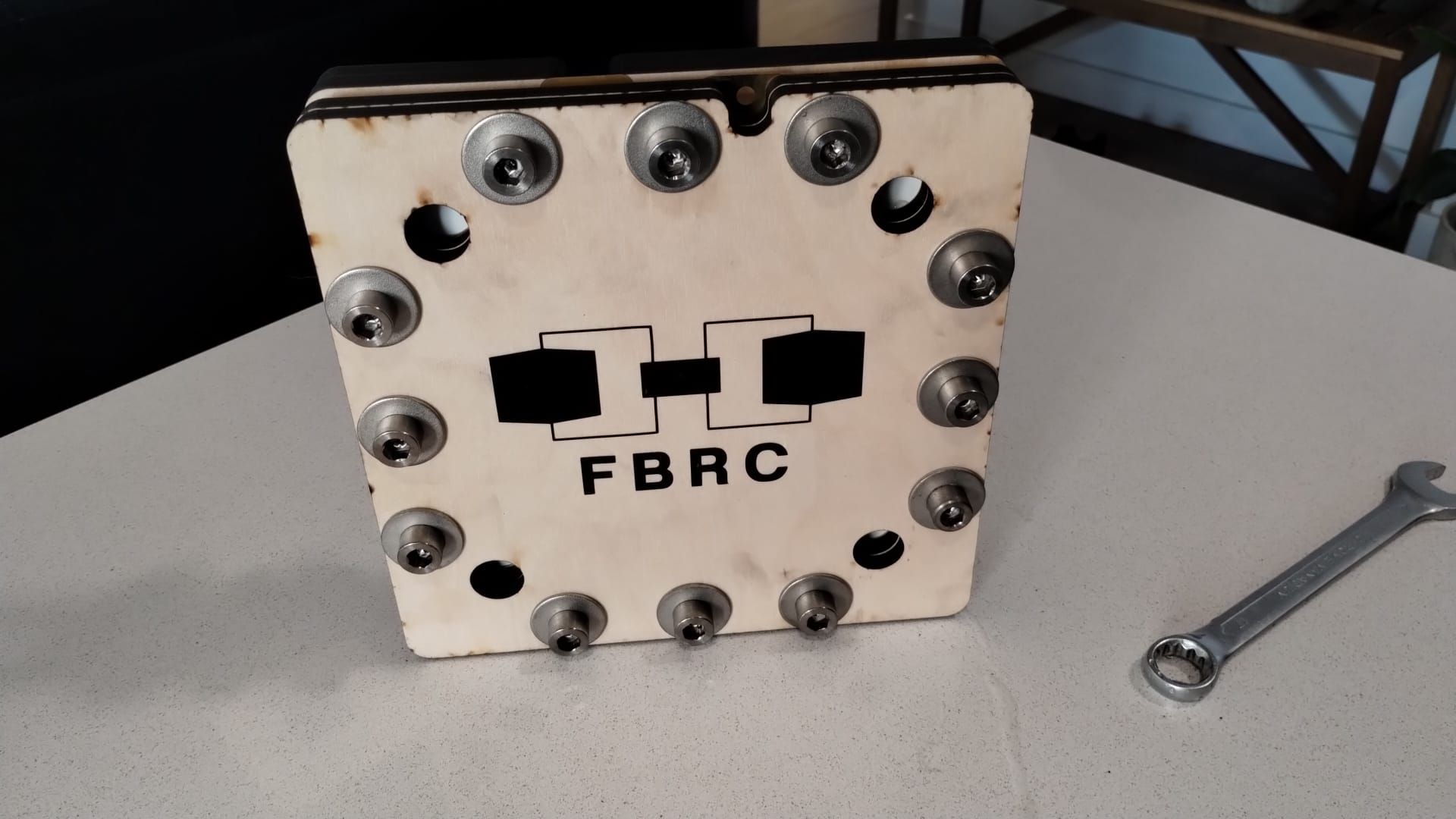
This circulated without any leaks, even lacking one of the endplates.
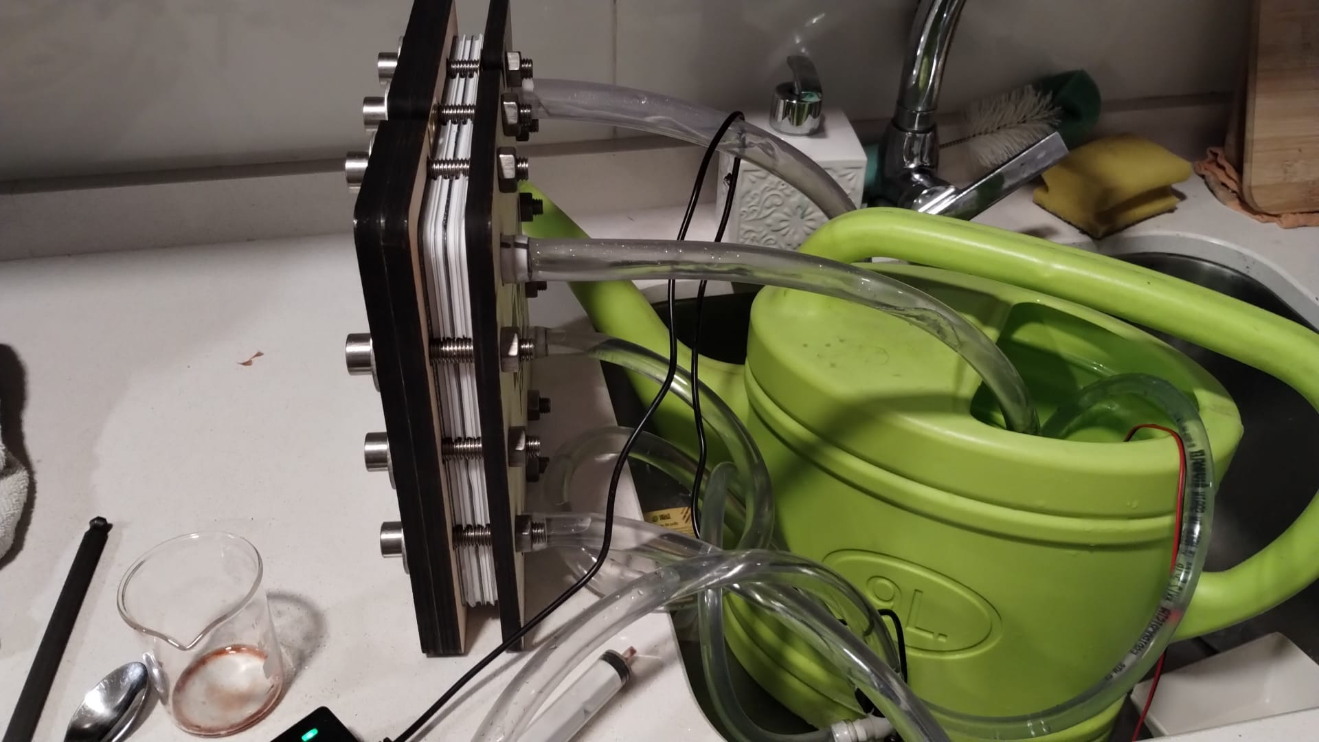
I will try doing a 3 cell stack, removing one of the other birch wood end plates.
Hello! It looks like you're interested in this conversation, but you don't have an account yet.
Getting fed up of having to scroll through the same posts each visit? When you register for an account, you'll always come back to exactly where you were before, and choose to be notified of new replies (either via email, or push notification). You'll also be able to save bookmarks and upvote posts to show your appreciation to other community members.
With your input, this post could be even better 💗
Register Login