Following your documentation – feedback & questions
-
@gus, awesome work! This is so exciting to see you've independently replicated the setup. Apologies on the delay for the pump wiring, I have recorded the raw video of me setting it all up as well as the pin numbers and I am in the process of editing it and updating the docs to match.
@gus said in Following your documentation – feedback & questions:
The new reservoirs seem fine now.
Did you encounter this problem too? How did you solve it?Our best strategy against leaking in PP prints has been 100% infill, 5 perimeters. I know some have success with slight overextrusion / flowrate multiplier of up to, say, 1.02 times. We have had reservoirs leak there before but tuning print settings usually leads to a tight reservoir. Could you share the file you modified? It looks like you added a big cylinder.
@gus said in Following your documentation – feedback & questions:
The cell itself doesn’t leak. I used a torque of 3 Nm for now, but it already looks slightly distorted. Have you considered using more bolts?
I think we need a stiffer endplate - similar hole pattern geometry, just thicker. This is an area to improve for sure, it's not ideal as-is. In the CAD files we have specified a 2D endplate (https://codeberg.org/FBRC/RFB-dev-kit/src/branch/main/CAD/exports/Metal Endplate.step), that could be laser cut or milled from aluminum. @danielfp@chemisting.com has received endplate versions of this in aluminum, the only catch is then you need insulating washers so as to not short them. Another rigid polymer could work too.
@gus said in Following your documentation – feedback & questions:
I also wanted to ask: is silicone resistant to this type of chemistry? Since it’s used for gaskets, maybe silicone tubing could be used as well?
We've tested and silicone tubing doesn't work for zinc-iodide, unfortunately. The gasket application of silicone is forgiving enough that it seems to work for this purpose, however, but we may be pushing our luck.
@gus said in Following your documentation – feedback & questions:
Regarding the Arduino program: it seems there are four defined pins — In1 (pin 9), In2 (pin 8), In3 (pin 7), and In4 (pin 6) — but they don't appear to serve any purpose.
These are legacy pins from when we used to use an H-bridge driver for different motors, before we got these stepper motors with built-in drivers.
This code is outdated, I have the new code but it's on my lab PC which is offline right now
 I am going to upload it soon.
@gus said in Following your documentation – feedback & questions:
As for the main Python program — should it work with no issues once the Arduino and MYSTAT are connected to the computer?
The program here * should * work on linux when run as root (in order to have proper USB access). You can control the pump speeds via the Arduino with the software, even without the MYSTAT connected (under the "charge/discharge" tab) (this will all hopefully be in a video soon!)
I'll have some more info soon (tomorrow hopefully?)
@kirk said in Following your documentation – feedback & questions:
In the CAD files we have specified a 2D endplate (https://codeberg.org/FBRC/RFB-dev-kit/src/branch/main/CAD/exports/Metal Endplate.step), that could be laser cut or milled from aluminum. @danielfp@chemisting.com has received endplate versions of this in aluminum, the only catch is then you need insulating washers so as to not short them. Another rigid polymer could work too.
I found a pic of this setup:
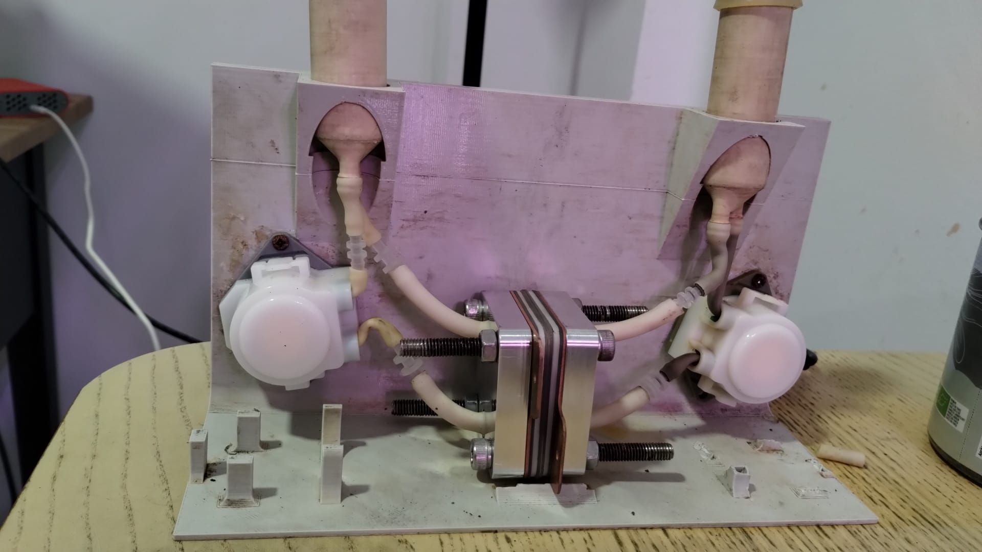
-
@kirk said in Following your documentation – feedback & questions:
Could you share the file you modified? It looks like you added a big cylinder.
I have send you an email,
@kirk said in Following your documentation – feedback & questions:
The program here * should * work on linux when run as root (in order to have proper USB access). You can control the pump speeds via the Arduino with the software, even without the MYSTAT connected (under the "charge/discharge" tab) (this will all hopefully be in a video soon!)
Thank you. I am planning to use a Raspberry Pi for long-term tests. Are you using a Raspberry Pi too, or a PC?
@kirk said in Following your documentation – feedback & questions:
In the CAD files we have specified a 2D endplate (https://codeberg.org/FBRC/RFB-dev-kit/src/branch/main/CAD/exports/Metal Endplate.step), that could be laser cut or milled from aluminum. @danielfp@chemisting.com has received endplate versions of this in aluminum, the only catch is then you need insulating washers so as to not short them. Another rigid polymer could work too.
Thank you. For now, if there are no leaks during the long-term tests, I will not change these endplates.
And also, I wanted to ask you about the current collector's material – is brass a better option than pure copper? What was the criterion for the material type and thickness selection?
-
@gus said in Following your documentation – feedback & questions:
I have send you an email,
Received, thank you!
@gus said in Following your documentation – feedback & questions:
Thank you. I am planning to use a Raspberry Pi for long-term tests. Are you using a Raspberry Pi too, or a PC?
I am using an old laptop that was in our lab, but a Raspberry Pi would work fine. I usually install ZeroTier or similar and then VNC in for remote access.
@gus said in Following your documentation – feedback & questions:
And also, I wanted to ask you about the current collector's material – is brass a better option than pure copper? What was the criterion for the material type and thickness selection?
Brass is somewhat more corrosion-resistant than copper, which is why we specified it. 1 mm is an arbitrary first guess for a reasonable thickness that's stiff and conductive enough, we haven't done any calculations for this however.
-
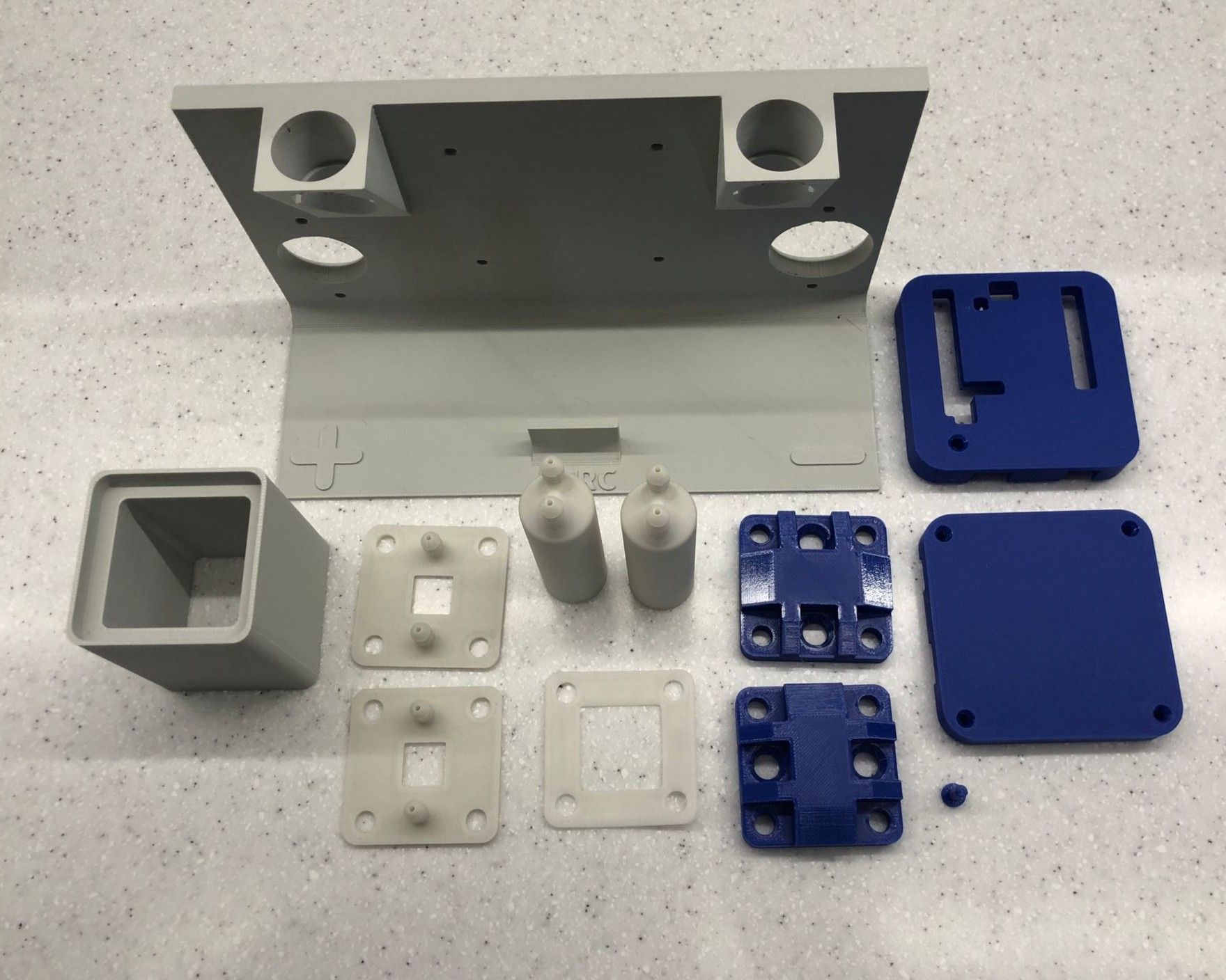
Also, apologies for the wait, but here are some more detailed instructions on how to build and wire everything (though you seem to have figured it out)
A video to accompany the written documentation: https://spectra.video/w/nJ8XNYu1MXNPSDLKV3KVTh
Improved documentation page on the electronics: https://fbrc.codeberg.page/rfb-dev-kit/electronics.html
-
It's been a while, but I’ve just configured a Raspberry Pi and got the mystat.py script working alongside Mystat and the Arduino. It looks like the chemistry is ready as well. Could I ask you for some instructions on how to proceed with the test using the mystat.py script? There are multiple options available, and I want to make sure everything is set up correctly
")
-
It's been a while, but I’ve just configured a Raspberry Pi and got the mystat.py script working alongside Mystat and the Arduino. It looks like the chemistry is ready as well. Could I ask you for some instructions on how to proceed with the test using the mystat.py script? There are multiple options available, and I want to make sure everything is set up correctly
@gus Nice work! Please let me know what electrolyte, concentration and volume you want to run and I can give you some guidance on exact settings.
-
@sepi, @danielfp248 thanks :), @danielfp248, I have an exact electrolyte from the documentation https://fbrc.codeberg.page/rfb-dev-kit/electrolyte.html .
-
@sepi, @danielfp248 thanks :), @danielfp248, I have an exact electrolyte from the documentation https://fbrc.codeberg.page/rfb-dev-kit/electrolyte.html .
@gus Great! As a first test please run the following:
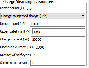
This should take around 1 one hour per charge/discharge cycle, experiment should take around 5 hours total. If the cycle ends because the potential reaches the upper safety limit too quickly, reduce the currents to 10000 and try again. At first the cells can require some time cycling at low SOC at lower current, to build all the Zn nucleation sites. Do not cycle to a potential higher than 1.7V because you will start having nasty side reactions at this point.
If this cycles successfully you can then increase the currents to 30000uA and repeat, see that it goes well.
After that you can then start going to high SOC values at 40000uA. I would recommend first cycling to 100mAh (set Upper bound to 100000uAh). Enclose the battery when cycling to higher SOC - you can put it inside a plastic tub - because leaks due to any problem will spray highly charged electrolyte, which, even if the volume is low, can be dangerous.
If you let me know how each test goes I can provide further feedback.
-
That sounds like even more exciting that I expected. @danielfp248 could you put this and a description of the wirering into the docs?
-
That sounds like even more exciting that I expected. @danielfp248 could you put this and a description of the wirering into the docs?
-
@gus Great! As a first test please run the following:
This should take around 1 one hour per charge/discharge cycle, experiment should take around 5 hours total. If the cycle ends because the potential reaches the upper safety limit too quickly, reduce the currents to 10000 and try again. At first the cells can require some time cycling at low SOC at lower current, to build all the Zn nucleation sites. Do not cycle to a potential higher than 1.7V because you will start having nasty side reactions at this point.
If this cycles successfully you can then increase the currents to 30000uA and repeat, see that it goes well.
After that you can then start going to high SOC values at 40000uA. I would recommend first cycling to 100mAh (set Upper bound to 100000uAh). Enclose the battery when cycling to higher SOC - you can put it inside a plastic tub - because leaks due to any problem will spray highly charged electrolyte, which, even if the volume is low, can be dangerous.
If you let me know how each test goes I can provide further feedback.
@danielfp248 said in Following your documentation – feedback & questions:
After that you can then start going to high SOC values at 40000uA. I would recommend first cycling to 100mAh (set Upper bound to 100000uAh). Enclose the battery when cycling to higher SOC - you can put it inside a plastic tub - because leaks due to any problem will spray highly charged electrolyte, which, even if the volume is low, can be dangerous.
Thank you for this advice. To be honest, I’m a little bit afraid of leaks that could damage the Arduino, above all. Do you propose covering just the cell, or the whole system? I’ve placed the system in an IKEA Samla box, and I can cover it, just making some holes for the cables. Do you recommend extra covering for the cell as well?
-
@danielfp248 said in Following your documentation – feedback & questions:
After that you can then start going to high SOC values at 40000uA. I would recommend first cycling to 100mAh (set Upper bound to 100000uAh). Enclose the battery when cycling to higher SOC - you can put it inside a plastic tub - because leaks due to any problem will spray highly charged electrolyte, which, even if the volume is low, can be dangerous.
Thank you for this advice. To be honest, I’m a little bit afraid of leaks that could damage the Arduino, above all. Do you propose covering just the cell, or the whole system? I’ve placed the system in an IKEA Samla box, and I can cover it, just making some holes for the cables. Do you recommend extra covering for the cell as well?
@gus no, that should be fine. Since all the tubing is at the front, leaks are usually contained to the front of the cell, I've never had a leak splash back and damage the Arduino, even when we didn't have it inside a box but just bare.
-
Another question before I start the test: I understand that I need to connect WE/SE to one electrode and CE/RE to the other. Does it matter which electrode is connected to which pair? Does the Mystat.py script differentiate between them?
@gus It doesn't matter on your first run, because the cell is perfectly symmetrical on start, but remember how you connect it as you would want to always connect it the same, this way elemental iodine will be limited to only one side of the cell. I always mark one of the endplates with an X to remember which one I connect as an anode and which one as a cathode. Where you connect WE/SE is where you will generate triiodide (your cathode) and where you connect CE/RE will be you will deposit Zn (your anode).
-
@danielfp248 Ok, thank you. So there is no need to assign one peristaltic pump to WE/SE and the other to CE/RE? Because if the electrodes are connected arbitrarily, this information will not be passed to mystat.py, right?
Edit: I suppose that I should connect the WE/RE to the electrode associated with the positive (P) pump circuit, and the CE to the electrode associated with the negative (N) pump circuit.
@gus It doesn't matter what side you connect to WE/SE the first time you run the setup. The pumps aren't really associated with the electrodes at all on the program. In a new setup both sides are exactly identical.
The important thing is, whichever side (pump, reservoir, electrode) you use for WE/SE the first time, always use the same side for WE/SE, always same pump, same electrode side, same reservoir, etc.
-
Ok, thank you @danielfp248 ! I know I'm probably being a pain, but I just wanted to be absolutely sure:) So this part is already solved.
However, I have found out that mystat.py was not able to save results to a file.
On the Raspberry Pi that I am using right now, I was unable to install PyQt5 in a virtual environment following your readme.txt and requirements.txt file. The problem is known and I have not found a working solution for the venv setup. As a workaround, I was using the default version of Python and libraries. This was probably causing the file saving issue.
Happily, the script seems to be working on the Raspberry Pi's default system Python and libraries after changing the "choose_file" function to the following:
def choose_file(file_entry_field, questionstring):
"""Open a file dialog and write the path of the selected file to a given entry field."""
filedialog = QtWidgets.QFileDialog()
# Get the tuple (filename, filter) and take only the filename
filename, _ = filedialog.getSaveFileName(mainwidget, questionstring, "", "ASCII data (*.txt)",options=QtWidgets.QFileDialog.DontConfirmOverwrite)
file_entry_field.setText(filename)I hope there will be no more incompatibility issues during battery testing
@gus Awesome, feel free to post screenshots of your testing! You can also post some of your result files here if you need any help plotting the results.
-
I’ve finally completed the first tests of the battery.
@danielfp248, I used the parameters you suggested, but I had to enter one of the currents (either charge or discharge) with a negative sign. With each subsequent cycle, the efficiency improved (as shown below). Is this difference in capacity from cycle to cycle expected?
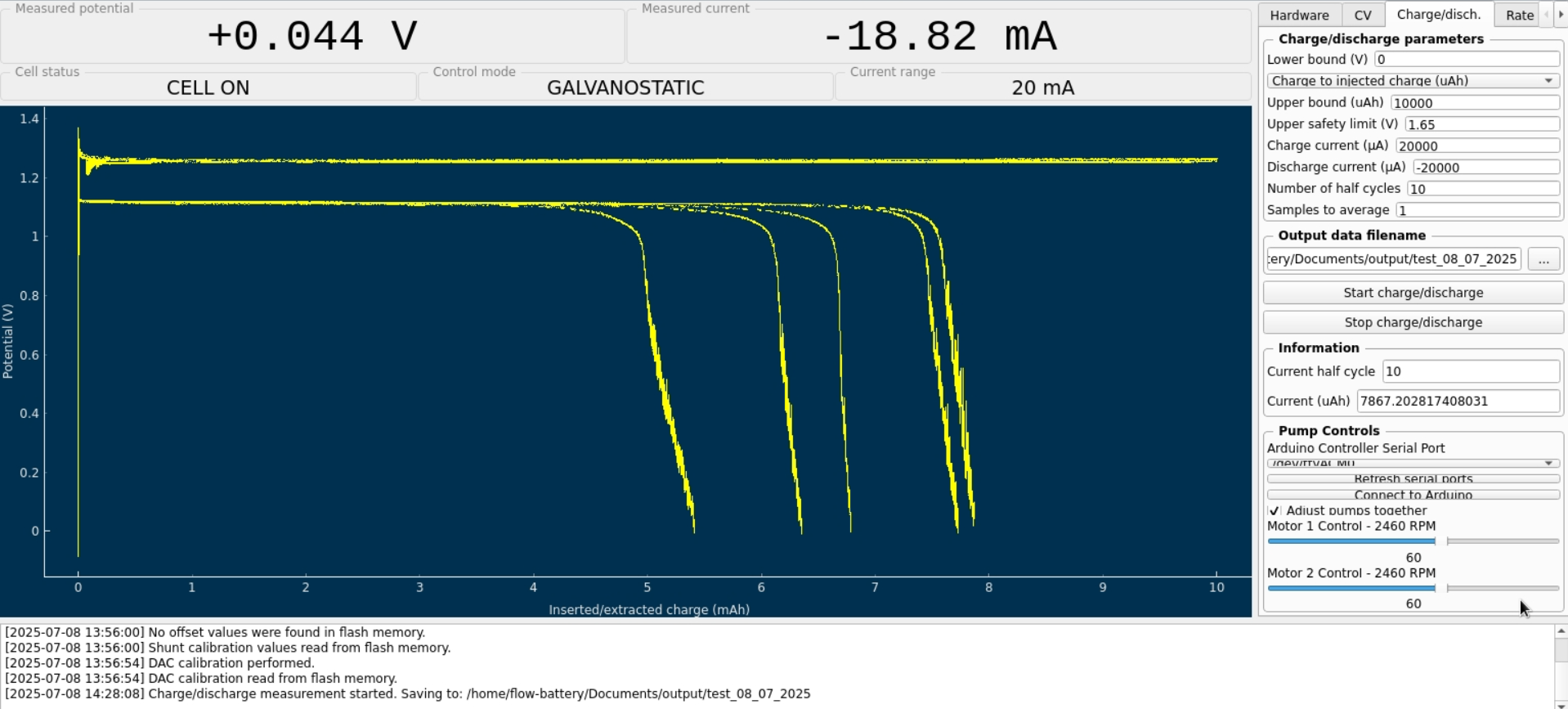
I expected the program to automatically adjust the pump RPMs, but it turned out I had to set them manually. I'm not sure if the values I chose were appropriate.
Now I understand why you mentioned that the connection combination didn’t make a difference
However, I still have some doubts about the resulting voltage value—doesn’t it seem too low?Before turning on the pumps, I zeroed Mystat. I’ve just realized that it should also be calibrated with a 1.000 kOhm resistor.
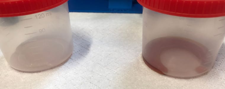
I used the tubing that came with the pumps. After completing five cycles, I emptied the electrolyte and rinsed the system several times with deionized water.
Now that I know the system works, I’ll look for proper electrolyte-resistant tubing and continue with further testing.
Here’s how the electrolyte’s color changed after just a few cycles:
Hello! It looks like you're interested in this conversation, but you don't have an account yet.
Getting fed up of having to scroll through the same posts each visit? When you register for an account, you'll always come back to exactly where you were before, and choose to be notified of new replies (either via email, or push notification). You'll also be able to save bookmarks and upvote posts to show your appreciation to other community members.
With your input, this post could be even better 💗
Register Login