Working on a large scale open source flow battery design and kit

-
During the past couple of years we have been working on the design of a small flow battery kit for the study of flow batteries (you can read a previous post about it here). With the help of an NLNet grant, we have fully developed the first two versions of our small scale kit – with the second one achieving even longer scale tests – and are now working on the development of a larger surface area kit that can be used to study flow batteries or build flow battery applications at a relevant scale for practical power storage.

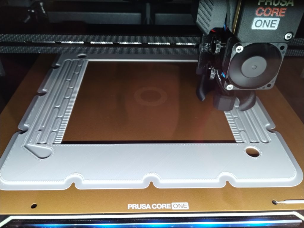
A flowframe being printed on our Prusa Core One on Polypropylene. Such a large flat area piece is very hard to print without warping in non-heated chambers. This new large area setup – which we have discussed in our forum – is now moving out of the design stage thanks to the acquisition of new systems for both 3D printing (Prusa Core One) and vinyl cutting (Cricut Maker4) that are allowing us to move to their in-house fabrication and testing. The new cell is designed to be compatible with the area of 3D printing beds and features an active area of 13.5×13.5cm, which is 182.5cm2. In practice this means a single cell will be able to handle a capacity of nearly 22Wh when using the Zn-I chemistry used in our small scale design.
We borrow some of the features that worked great for our small scale kit – like using a polypropylene enclosed flow frame – and add features that are needed for a scalable design (like all entry/exit points on the same side, stacking compatible design, etc).
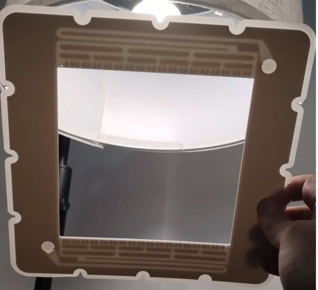
Finished flow frame held against light so that you can see the flow field design. This design is not final and will change as we do fluid testing. The fabrication of these pieces is especially challenging due to their size and the complexity of the flow fields in them. The flow fields have to follow complex paths to prevent the creation of large shunt currents within the device. A really good 3D printer with a heated enclosure is required to be able to print this in polypropylene with no warping and good enough resolution. Even with such a printer, a lot of fine tuning is still required to achieve the low level of surface roughness and high level of water tightness that is needed for this particular application.
While we are thinking about the potential of using heat welding or even adhesives to be able to put the cell together, the easiest first approach will be to use the same silicon gaskets as we used for the fabrication of our initial cells. To cut our gaskets in house we are using a Cricut Maker4 vynil cutter, which is able to make this high precision cuts without any problems.
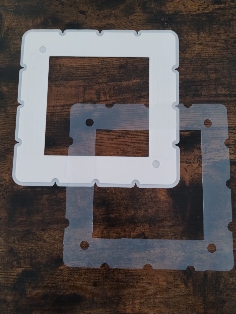
One of our 3D printed polypropylene flow frames next to a silicone gasket With these materials now fabricated, we are now close to putting together our first tests of a larger scale flow battery cell. The idea of these initial tests will be to test the cell for leaks and make sure we can circulate water without problems before we try to run any active materials. We will be using thick wood as endplates for this initial test, as this is the easiest to source, hard material, that can be used. Thanks to our use of fully enclosed gaskets, the end plates will also have zero contact with any water or active materials.

This flow battery kit work is being funded by the Financed by Nlnet’s NGI0 Entrust Fund. We are also collaborating with the FAIR Battery project.
-
During the past couple of years we have been working on the design of a small flow battery kit for the study of flow batteries (you can read a previous post about it here). With the help of an NLNet grant, we have fully developed the first two versions of our small scale kit – with the second one achieving even longer scale tests – and are now working on the development of a larger surface area kit that can be used to study flow batteries or build flow battery applications at a relevant scale for practical power storage.
A flowframe being printed on our Prusa Core One on Polypropylene. Such a large flat area piece is very hard to print without warping in non-heated chambers. This new large area setup – which we have discussed in our forum – is now moving out of the design stage thanks to the acquisition of new systems for both 3D printing (Prusa Core One) and vinyl cutting (Cricut Maker4) that are allowing us to move to their in-house fabrication and testing. The new cell is designed to be compatible with the area of 3D printing beds and features an active area of 13.5×13.5cm, which is 182.5cm2. In practice this means a single cell will be able to handle a capacity of nearly 22Wh when using the Zn-I chemistry used in our small scale design.
We borrow some of the features that worked great for our small scale kit – like using a polypropylene enclosed flow frame – and add features that are needed for a scalable design (like all entry/exit points on the same side, stacking compatible design, etc).
Finished flow frame held against light so that you can see the flow field design. This design is not final and will change as we do fluid testing. The fabrication of these pieces is especially challenging due to their size and the complexity of the flow fields in them. The flow fields have to follow complex paths to prevent the creation of large shunt currents within the device. A really good 3D printer with a heated enclosure is required to be able to print this in polypropylene with no warping and good enough resolution. Even with such a printer, a lot of fine tuning is still required to achieve the low level of surface roughness and high level of water tightness that is needed for this particular application.
While we are thinking about the potential of using heat welding or even adhesives to be able to put the cell together, the easiest first approach will be to use the same silicon gaskets as we used for the fabrication of our initial cells. To cut our gaskets in house we are using a Cricut Maker4 vynil cutter, which is able to make this high precision cuts without any problems.
One of our 3D printed polypropylene flow frames next to a silicone gasket With these materials now fabricated, we are now close to putting together our first tests of a larger scale flow battery cell. The idea of these initial tests will be to test the cell for leaks and make sure we can circulate water without problems before we try to run any active materials. We will be using thick wood as endplates for this initial test, as this is the easiest to source, hard material, that can be used. Thanks to our use of fully enclosed gaskets, the end plates will also have zero contact with any water or active materials.
This flow battery kit work is being funded by the Financed by Nlnet’s NGI0 Entrust Fund. We are also collaborating with the FAIR Battery project.
@danielfp is this at a point where it would be useful to have people trying to replicate some of it? i have the tools needed to build something like this and would be interested in doing that if it would be helpful to you to see how replicable some of this is.
-
@danielfp is this at a point where it would be useful to have people trying to replicate some of it? i have the tools needed to build something like this and would be interested in doing that if it would be helpful to you to see how replicable some of this is.
@alive Thanks! I would prefer to build a suitable prototype before anyone tries to reproduce, to make sure you don’t waste time building iterations that might not work. Once I have something that we’re sure doesn’t leak I’ll let you know so that you can help. Thanks for offering!
-
@alive Thanks! I would prefer to build a suitable prototype before anyone tries to reproduce, to make sure you don’t waste time building iterations that might not work. Once I have something that we’re sure doesn’t leak I’ll let you know so that you can help. Thanks for offering!
@danielfp that makes sense! perhaps i'll take a crack at building one of the smaller ones in the meantime to get some practice — it looks like that design is fairly stable?
-
 K kirk shared this topic on
-
@danielfp that makes sense! perhaps i'll take a crack at building one of the smaller ones in the meantime to get some practice — it looks like that design is fairly stable?
@alive The small kit design is stable. We fully encourage you to give that a try and share your results with us!
-
It seems to me that milling would be much easier for the flow gasket. What do you think? Also maybe could you print the flow frame from TPU, thus maybe eliminating the need for the gaskets? Of you need a very even finish, the ironing option of slicers might be of interest.
-
It seems to me that milling would be much easier for the flow gasket. What do you think? Also maybe could you print the flow frame from TPU, thus maybe eliminating the need for the gaskets? Of you need a very even finish, the ironing option of slicers might be of interest.
Thanks for posting! To answer your questions:
1. Milling wouldn’t work because the flow frame has to be enclosed. If the flow frame was open we could do it with milling but since the flow frame flow fields are entirely enclosed, the only manufacturing technique that can easily do it is 3d printing.
2. TPU is not chemically compatible with the electrolytes we have used or others that are potentially interesting for people to test.
3. The ironing option actually creates rougher surfaces (basically less even) than the normal finish.
-
Thanks for the quick reply! About 1): why does the flow frame need to be closed? Could you not have two "layers" of a sandwich. One being milled with the fields and one bein just a sheet. Would that create leakage and manufacturing complexity issues? 2) Yeah, I don't know enough about chemistry to really asess this. 3) that's surprising but also maybe not that much.
Thanks for posting! Let me reply to your comments:
1. It doesn’t have to but it does make the cell much more stable. This is because upon compression gaskets can insert into flow channels and can then expand and create flow issues. You cannot just sandwich two layers without gaskets or adhesives because they will leak (we also tried this). We have found closed flow frames to be much more stable and leak-tight in our experiments, in the end the manufacturing process is also simpler, given that it is just 3d printing. Also note that very few materials are chemically compatible.
2. Very few materials are chemically compatible. PP is the only 3d printed material that fits the bill. Not even ABS is chemically compatible with iodine chemistry.
3. The problem is that it creates buildups of material in some areas, since the hot material effectively gets “pushed around” to even the surface. So you get smoother spots but then lots of ridges/valleys or sharp defects that are much harder to seal.
-
I was thinking of casting (posted in the other thread), but if you are printing enclosed complex channels, that would be a problem. I didn't think you could print horizontal channels without the material sagging into the channel.
I can see that unless the gasket was supper thin, it could squeeze into the channels in a layered design. But something applied in a thin liquid form such as an adhesive might work. I just googled the printer and cutter you're using to make the plates and gaskets. Some $1300 for both, ouch.
Thanks for posting!
Consider that exposing gasketing material to the solution can also cause it to deform due to interactions with the charged electrolyte. Silicone gaskets for example will expand through this mechanism and this is the main reason why they go into flow paths (not just because of compression).
Adhesives are a potential answer and this is something we might potentially explore, they are difficult though because polypropylene doesn’t stick to anything. Heat welding might be a more feasible path when using this plastic.
About the cutter and 3d printer, yes, they are expensive! Thanks to NLNet for their financing or we wouldn’t be able to do all of this. However, once we finalize all designs you could either have them made by a manufacturer like SendcutSend or Xometry for a decent price or we could potentially sell pieces at some point if there is enough interest.
-
The other post I was referring to was in "Designing the large-format cell". I was wondering if there are option to cast using resins or other material instead of printing. Would solve the problem of trying to print large plates without warping.
@Vorg I'm no expert in manufacturing, if you find anything that would work and you want to try it please feel free to share your results!
-
I'm no expert ether. We used quick setting plaster a lot in construction for repairs on a lot of things and now they have a "wood epoxy" which is an epoxy for wood repairs. You have a thing epoxy you brush on onto wood which provides a good bonding surface for dry rotted wood and then you mix an epoxy that works more like the quick setting plaster and creates a strong enough repair that you can nail it. These plasters and epoxies could be formed or poured to create a nice mold. For the quickset we could build up an area, then carve and shape it before it fully set. The surface is very smooth and with a spray sealer of some kind should be even better for molds.
A quick look into casting, it looks like the most common is using silicon for making the mold. Yes it lets you do detail, but it is also soft and flexible. Not good for making thin plates without warpage.
Hello! It looks like you're interested in this conversation, but you don't have an account yet.
Getting fed up of having to scroll through the same posts each visit? When you register for an account, you'll always come back to exactly where you were before, and choose to be notified of new replies (either via email, or push notification). You'll also be able to save bookmarks and upvote posts to show your appreciation to other community members.
With your input, this post could be even better 💗
Register Login