@gus Thanks for writing about your experience and again for reproducing the kit!
One of the issues of the Zn-I chemistry is that I2 can easily generate if the local concentration of iodide is not high enough. This can happen due to several reasons. For example if the electrolyte is not circulated fast enough, if the state of charge is too high or if the current is too high. The triethylene glycol helps avoid this, but it also runs into a limit if the right circumstances happen.
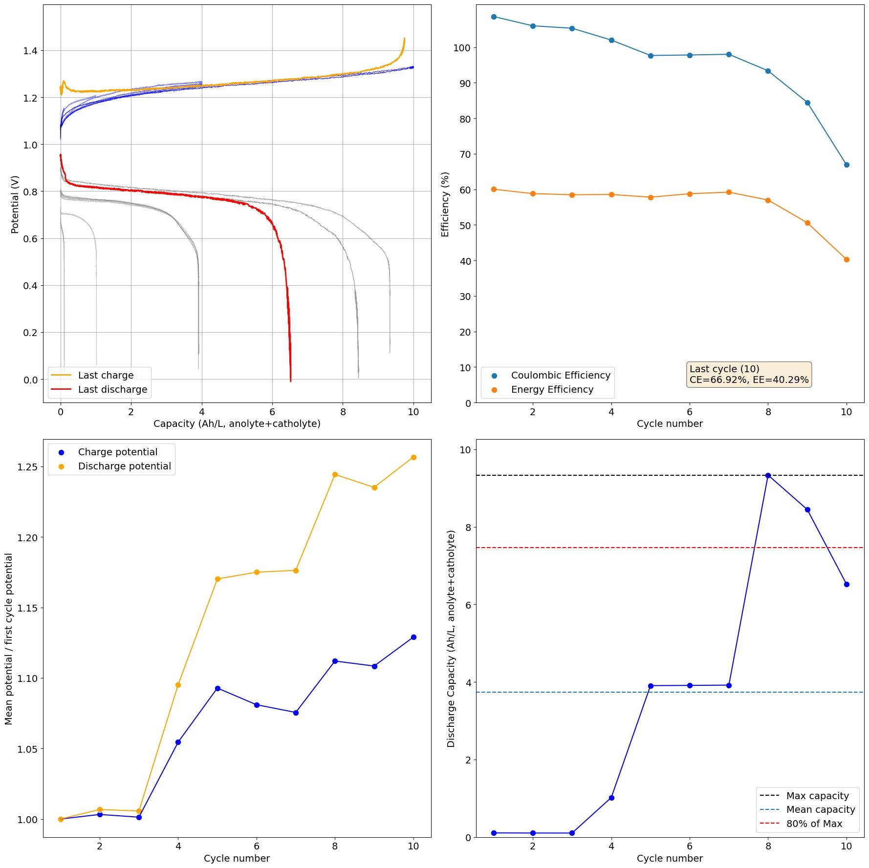
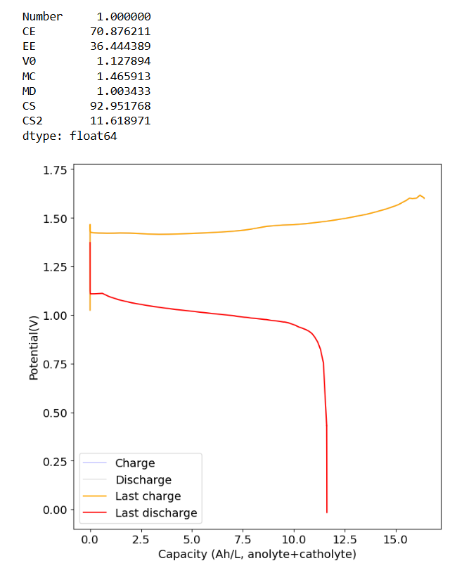
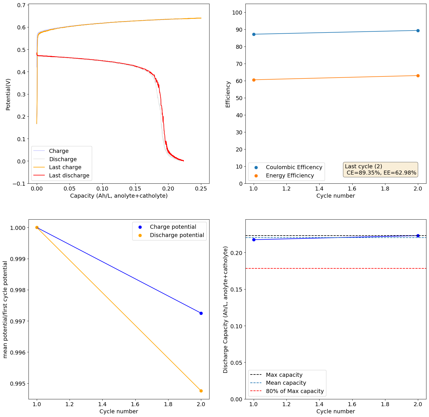
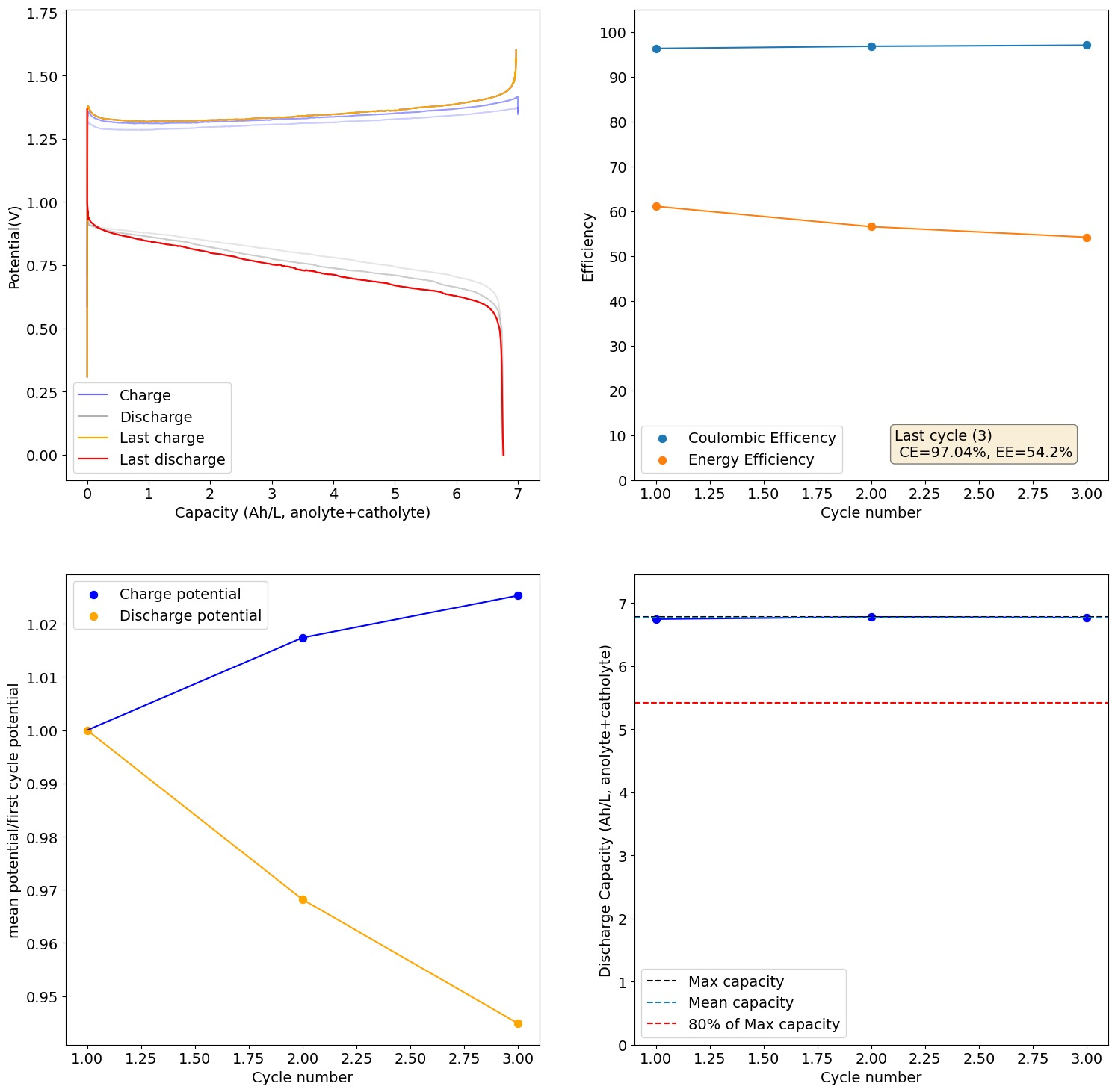
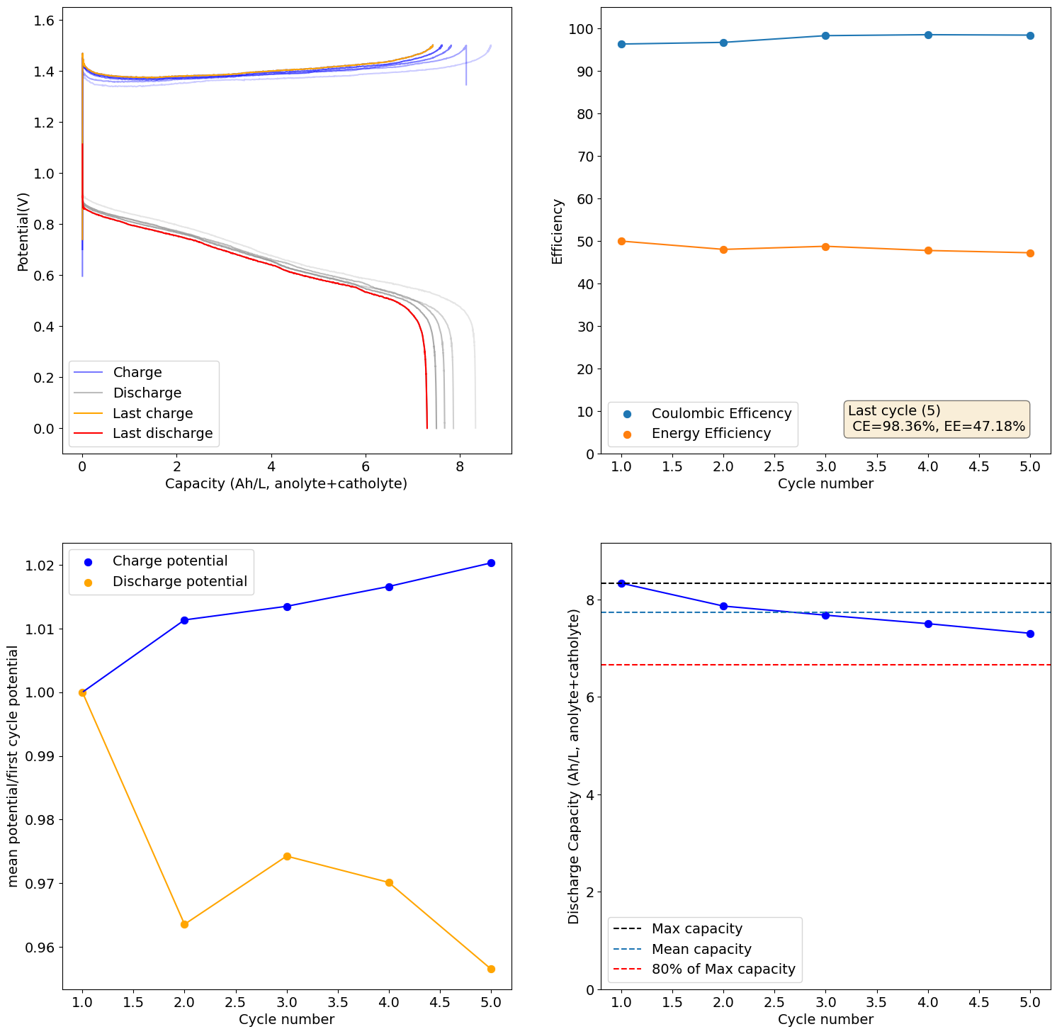
The electrolyte we suggest for testing is 2M I and 1M Zn. The max expected capacity of this electrolyte would be 17.6Ah/L, which our setup (if you use 5mL per side) would be around 176mAh. The 166Wh/L value from the paper you quote has to be interpreted carefully. First, consider that this value is measured in a 5M ZnI2 electrolyte, which is 10M I2, it is 5x as concentrated as the electrolyte we use. Second, this value reported on the paper is accounting for the catholyte volume only, so the actual total Wh/L has to be divided by 2 to compare with the values above, so it would be 83Wh/L. For our electrolyte 5x more concentrated we would expect to get 88Ah/L (105Wh/L at a voltage of 1.2V) which would be higher than the paper you cited, because we indeed expect to extract more capacity because of the use of triethylene glycol.
With that said, Zn-I is a hybrid battery (as you plate a metal) so the mAh/cm2 is also important. If you plate too much Zn not only do you get Zn dendrites but the setup will also clog because of the metal deposition process clogging the felt. The paper you cite uses a cell with an area of 40cm2 but the volume of electrolyte is never disclosed, so we don't know how much they plated in terms of mAh/cm2. However, other Zn-I literature suggests we shouldn't attempt to go above 100mAh/cm2, the lower the safer. For this paper I suspect this value was below the 10mAh/cm2 mark because of the lack of dendrites and the thickness of the membrane. This however means that in our system at 2cm2 we shouldn't charge above 200mAh, so even if we increased electrolyte concentration our max capacity is going to be limited to around 20Ah/L, perhaps we can push this to 26-30Ah/L by reducing volume, but I'm afraid not much more beyond that.
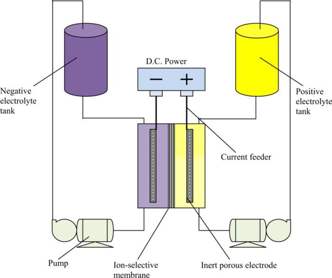
The membrane is another key point. The nafion membranes typically used are much lower resistance and much higher conductivity than a membrane like photopaper. While photopaper works well for demonstrating the cell, its resistance is going to be much higher and therefore our energy efficiencies and current densities will be much lower. If you contact me by chat I can mail you some daramic, which is a commercial microporous membrane, so that you can test it out and get better capacities. Another alternative is to modify photopaper (for example with PVA) to be able to use a single layer.
To answer your questions:
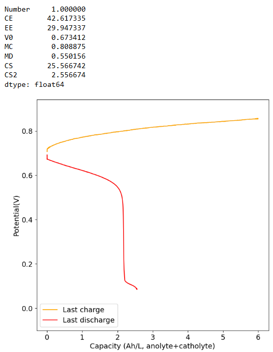
Do you have any advice for me? Where could the root cause of my failures be? - I wouldn't call your results a failure! I think you're doing well. Your charge/discharge curve looks great. You can try the following things:
- Try decreasing your current to 20mA and see if this way you can charge to the higher SOC, this will show if the problem is just your current density and transfer speeds.
- Also you can try activating your felt by putting it in commercial bleach for 48 hours, then washing it with distilled water thoroughly before using it. This improves the wetting of the felt a lot and helps the kinetics of the electrochemical reactions.
- Decrease your volume per side to 4mL, this will reduce the mAh/cm2 which will make clogging less likely as the SOC climbs.
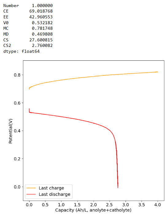
Am I definitely not supposed to use polypropylene felt on the catholyte side? You get best results without polypropylene on either side. Change to felt on both sides to get better SOC values. We also never used it on the catholyte side only on the anolyte side. If you use nonconductive felt on both sides you will reduce the chances of clogging but your energy efficiency will be dramatically lower.
Could there be an issue with the material quality I'm using (even though everything was purchased according to the Bill of Materials sources)? I don't think so, if you got everything from the BOM, then everything should be the exact same I have.
Let me know how things go!