This circulated without any leaks, even lacking one of the endplates.
I will try doing a 3 cell stack, removing one of the other birch wood end plates.
This circulated without any leaks, even lacking one of the endplates.
I will try doing a 3 cell stack, removing one of the other birch wood end plates.
I was doing a literature review of Fe/Mn the other day and happened to find this article on Fe/Mn using MSA (https://www.sciencedirect.com/science/article/pii/S001346862030637X). This article uses an asymmetric setup with FeCl3 on one side (paper says it's FeCl2 but that must be a mistake because the reaction requires Fe reduction on charge) and MnCl2 on the other, both sides using 3M methanesulfonic acid, separated by a Nafion membrane. The Mn3+ is in theory stabilized in the acid media, but given the color of the solution it might be that MnO2 nanoparticles are stabilized instead.
While the paper does not use this in a symmetric setup, I see no reason why this reaction couldn't work symmetrically so I prepared an electrolyte using the following:
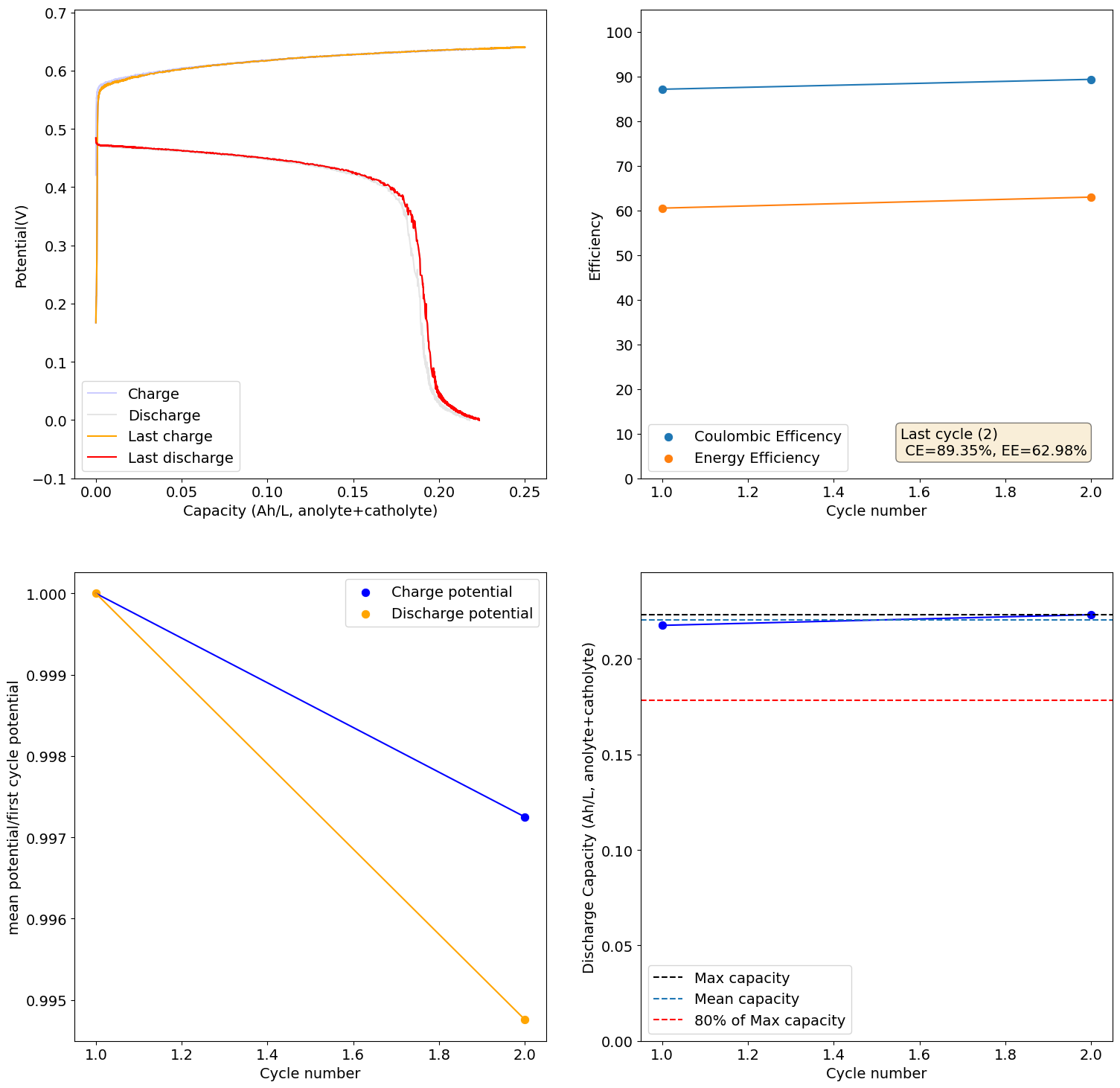
The above creates a solution that is around 1.5M Fe, 1.5M Mn and 3M MSA. This setup has the advantage that both reactions generate no solid products. At a 100% SOC this would give us ~20Ah/L. On charge:
Fe3+ + e- -> Fe2+
Mn2+ -> Mn3+ + e-
The potential difference between these two half reactions is not very high though, so the total expected cell voltage is ~550mV. However this is a "true flow battery" in that power and capacity are fully decoupled as the reaction products are all in solution. Note that Mn3+ is expected to have limited stability, especially at high concentrations, so I would expect capacity to degrade heavily as the Mn3+ gets converted into MnO2, unless this MnO2 is somehow stabilized in solution (which could be as nanoparticles). Interestingly Fe2+ can react with MnO2, so the battery might also self-heal if this happens, just temporarily capacity in the process.
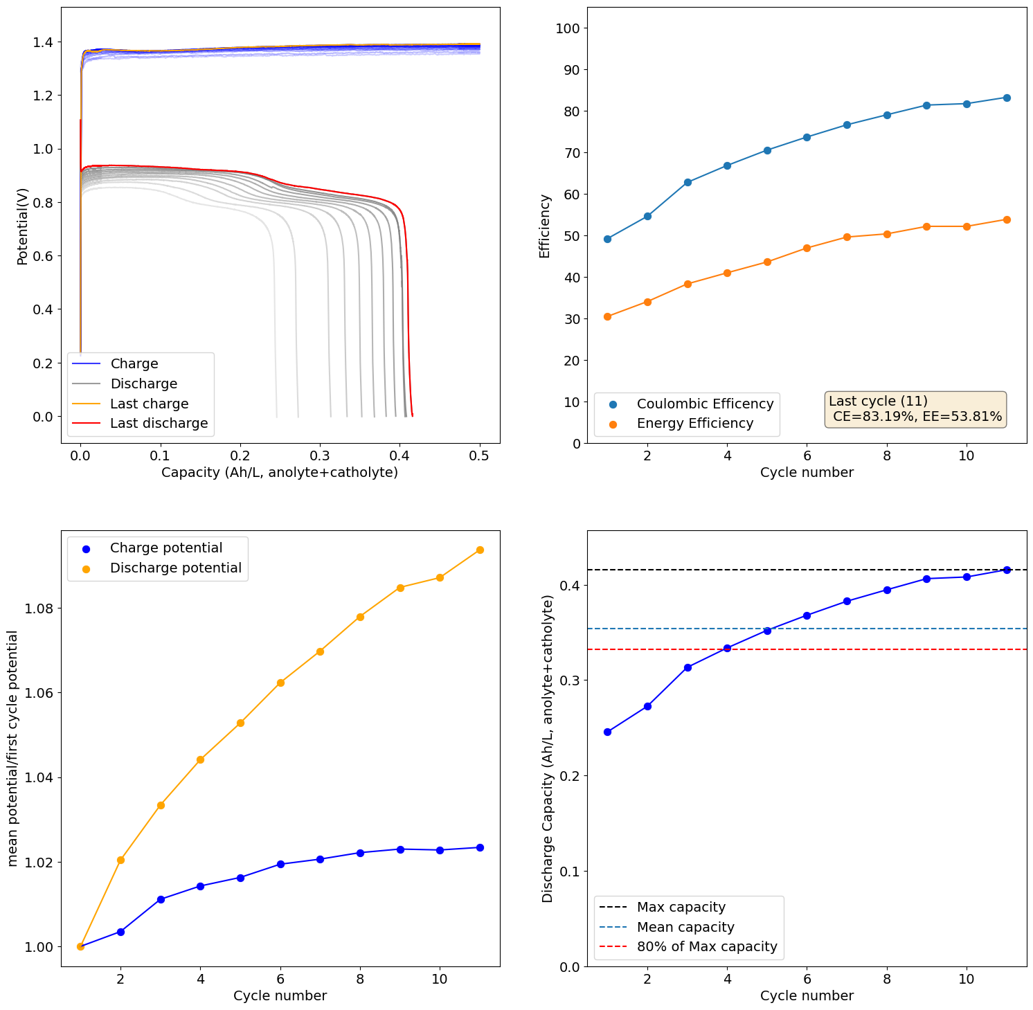
I loaded the electrolyte in a cell with carbon felt on both anode and cathode and used Daramic as a separator (cannot use paper as it reacts with Mn3+). Below are the results of a few cycles at low capacity (0.25Ah/L at 10mA/cm2), just to test the chemistry. It seems to work quite well:
I will continue to run some tests and will let you know what I get.
Since our design prevents direct contact with the current collector, almost any metal should work. you could even use aluminum foil if you really don't want to machine anything (although I wouldn't recommend it! lol). Bear in mind that the graphite foil is not impervious to the electrolyte, it diffuses slowly through it, so if you have highly charged electrolyte some reactivity with the current collector will happen through time (across weeks of cycling).
There is a paper on creating an electrode using graphoil and wax that might be much better (https://chemistry-europe.onlinelibrary.wiley.com/doi/abs/10.1002/slct.202103996). I will probably get a rosin press to test this and construct some better quality electrodes for our kits.
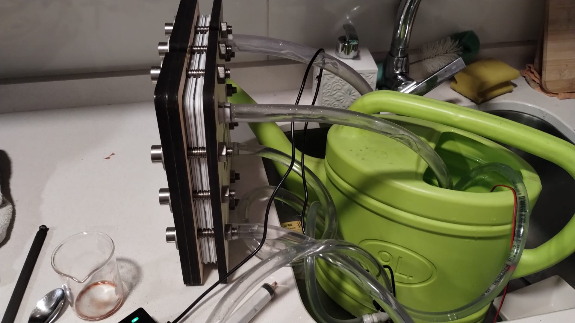
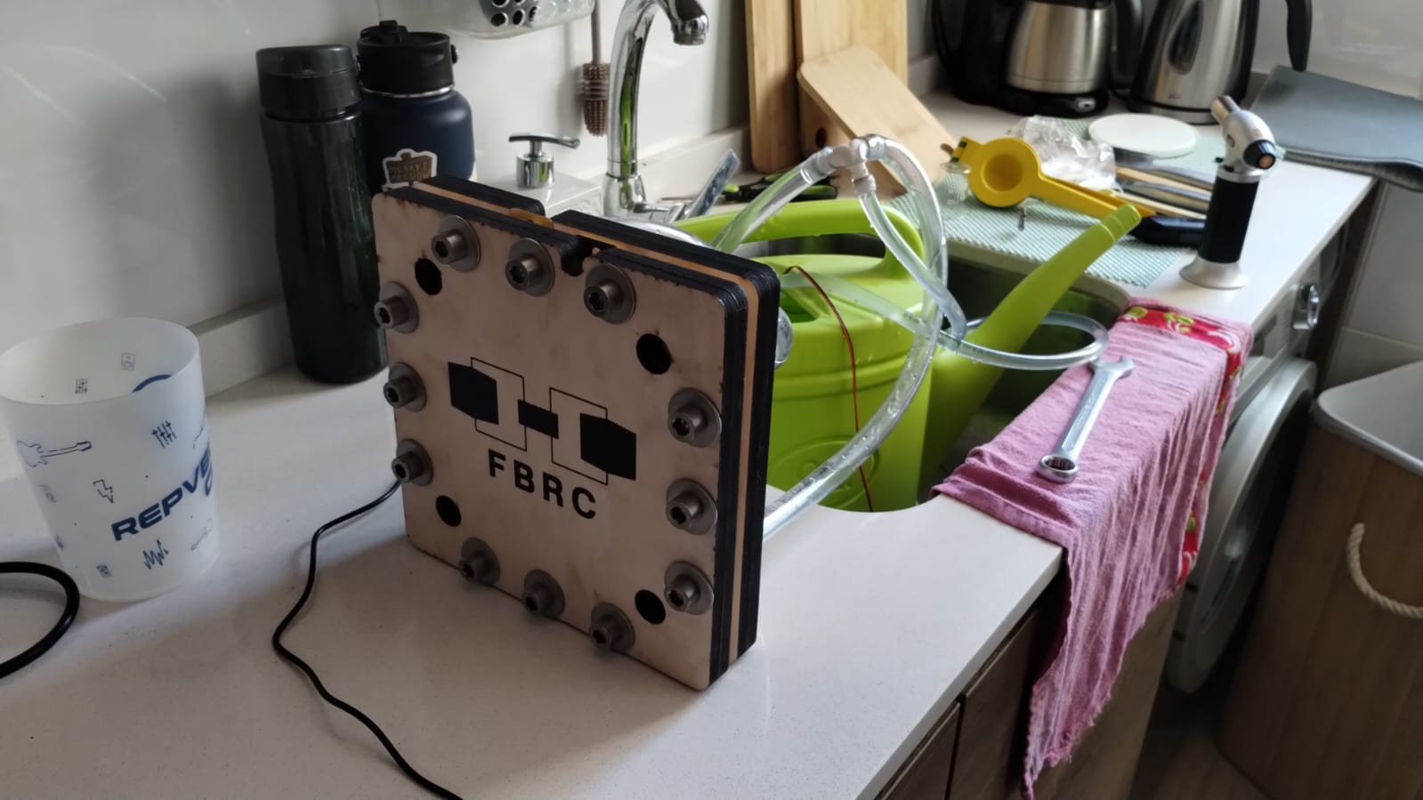
I just put together the first large scale cell and did a test with tap water recirculation to test if the geometry would work with no leaks. I didn't use any grafoil but just the bare brass current collectors, since I'm not doing any electrochemical testing right now.
There was a significant leak from one of the input ports as the pressure required to flow through the flow frame geometry was too high, but there were no leaks through the gaskets. We are going to be modifying the flow frame geometry to be the simplest possible, similar to the small scale kit. This way we can make sure we have a design that can flow at the lowest possible pressure and then we can scale complexity as required later on to improve shunt currents. We might also add barbs to the input ports to prevent this sort of leaking. We'll keep you posted on our progress!
Also, the wood did not warp on compression!
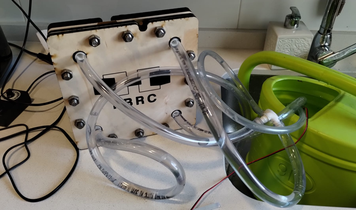
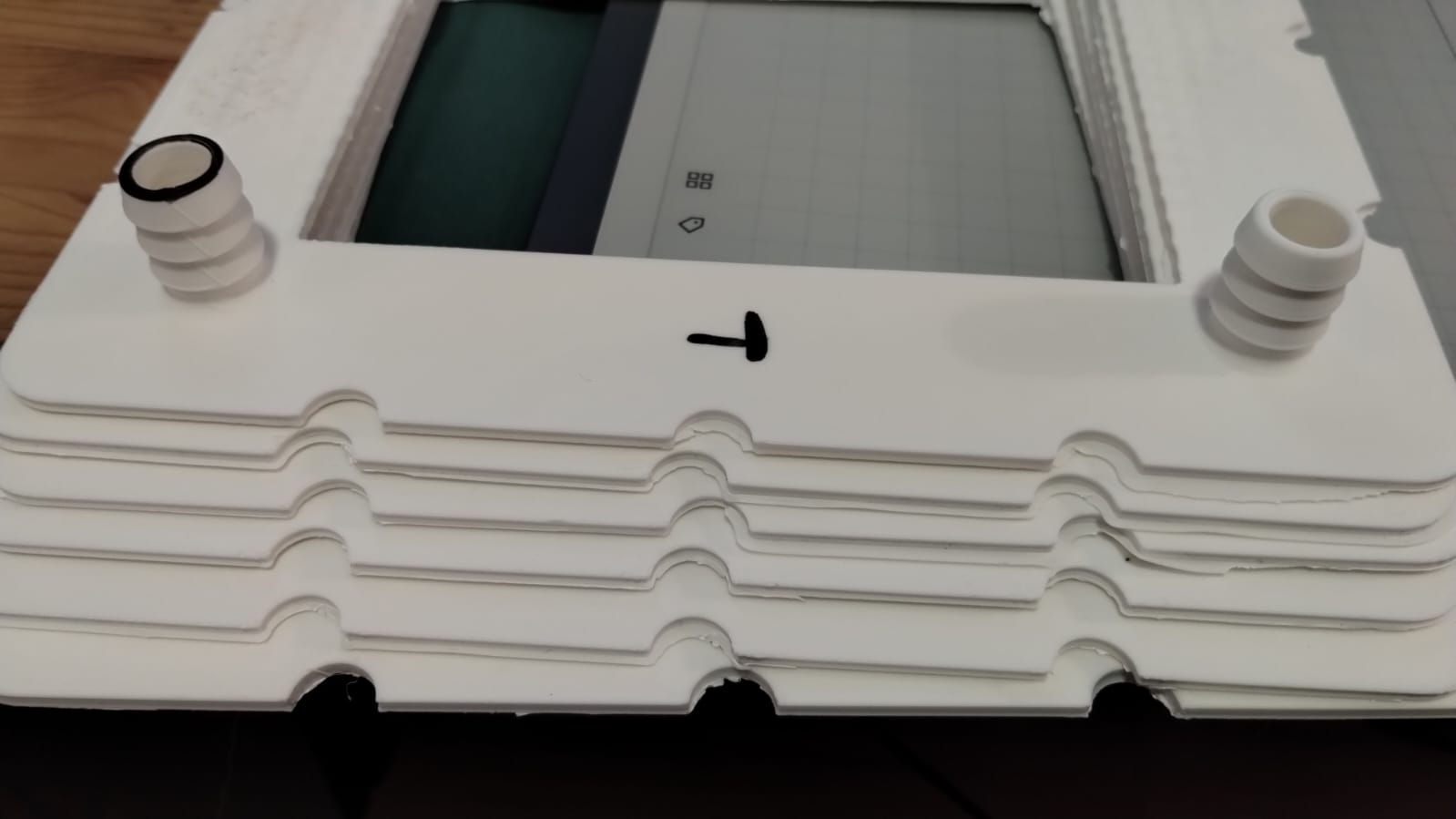
Just wanted to say I've made the first successful flow test of the large scale system. Kirk modified the flow frames to a much more simplified design for the flow path, which greatly reduced pressure and allowed flow without leaking. You can see the simpler flow path in the image below. Barbs were also added to the entry ports to prevent leaks around the hose due to pressure. Both flow frames printed water tight on my Prusa Core One.
For the first test I used a single pump and flowed tap water through both chambers. I used 4 layers of photopaper as a membrane material.
I tightened everything by hand and was actually missing washers on the backside (forgot to order enough, lol). Test went well, with over 30 minutes of flow at 5-10L/min with no leaks. At very high flow ~40L/min, I did start to see some leaks through the 0.1mm silicone gasket due to overpressure. With that said, this flow rate is extremely high, ready far above anything that we would ever need and was just a stress test.
For future reference I attach the configuration file used for these prints. large_scale_flowframe_config.txt
This is the filament I normally use https://www.smartmaterials3d.com/pp-filamento#/25-color-natural/27-diametro-285_mm/239-tamano-m_650g
Hey Everyone. I designed and printed some PLA sleeves to go over M6 screws so that you don't need to use tape on the screws anymore with the kit. The tape is often hard to properly wrap around and imo has to be changed quite often, so this should improve the design. I printed these on a Prusa Core One using a 0.4mm diameter nozzle. The screws don't come into contact with active material, so you can use PLA for this (doesn't have to be PP, although this should also work).
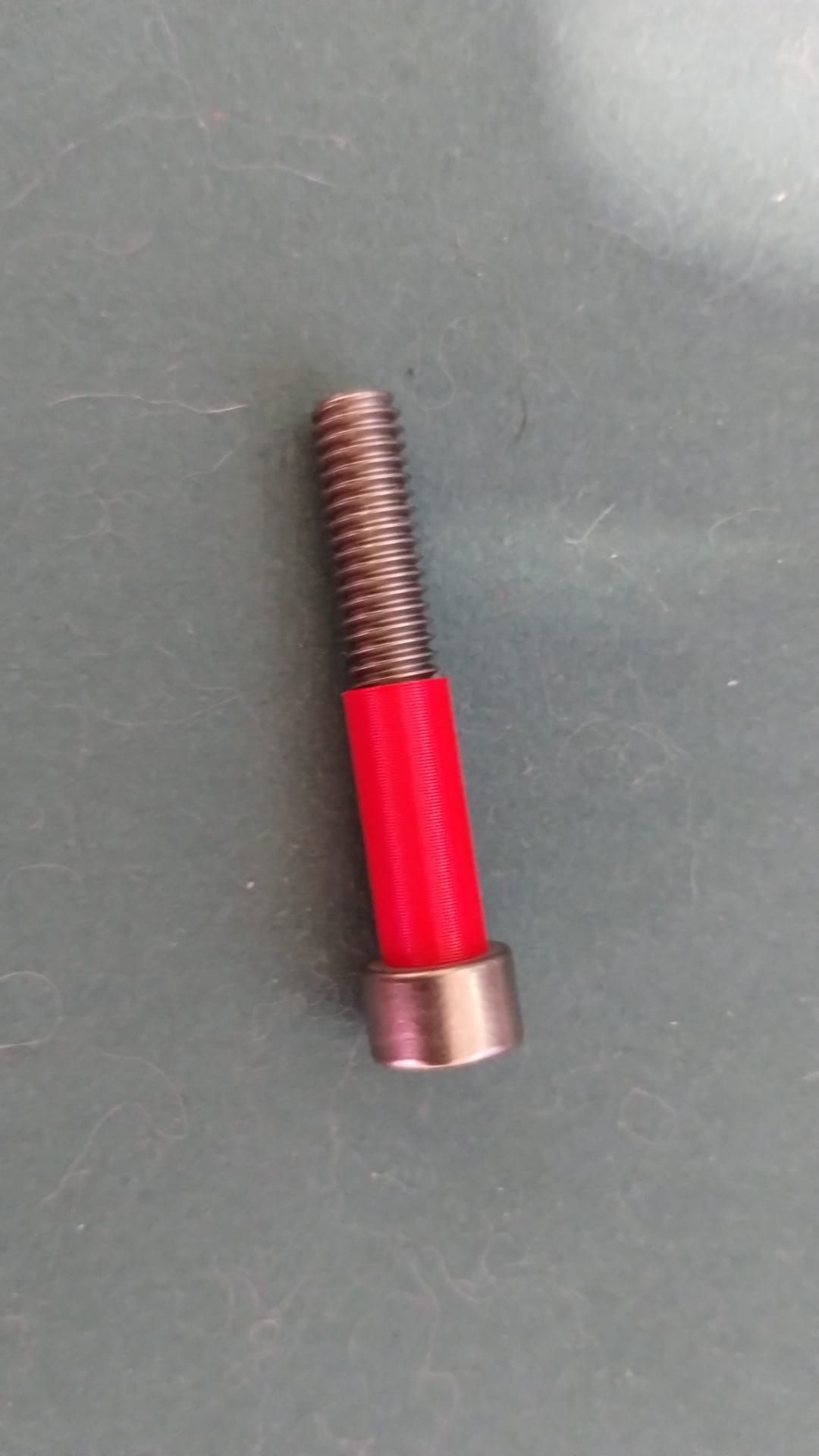
You can get the STL here:
You can print these in "vase mode" so that you have no stitching marks. Let me know what your experience is with other printers!
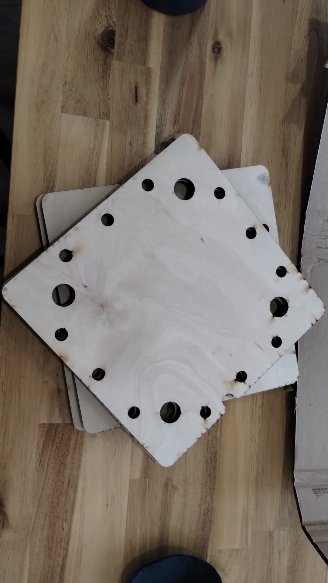
First stack assembly. This stack contains two cells. My screws weren't long enough so I had to sacrifice using one of the birch wood endplates to have it seal. Hopefully it doesn't leak!
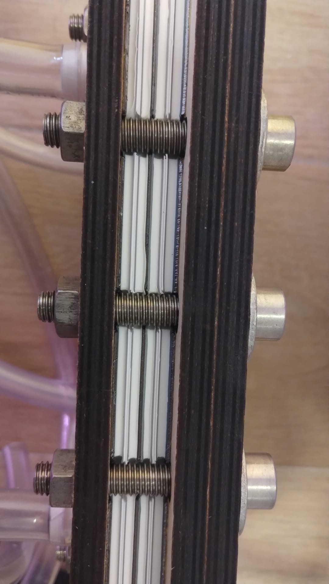
I will keep you guys posted. I will leak test this and then mail it to kirk for testing with real electrolyte.
@muntasirms Thanks for sharing. This is all very interesting. I have made several experiments with Zn/Fe fully symmetric cells (since Zn plates preferably over Fe), using glycine as a chelating agent to make sure Fe stays soluble at mildly acidic pH on the catholyte side. It hasn't really worked very well, I see big increases in ohmic resistance as a function of time, but I don't see any iron oxides forming on the cathode or on the membrane. I don't see full dissolution of the plated metal though, so I bet it has something to do with the oxidation of that metallic deposit (since probably some Fe+Zn alloy is depositing anyway).
I have never tried WISE electrolytes in flow batteries, and had actually never read the Fe+MgCl2 paper you mentioned. I just ordered MgCl2 and CaCl2, so I'll give that a try as soon as I have those salts! If we can get 1M FeCl2 work with MgCl2, then that would be amazing as a demonstration for the kit at both small and large scales.
I think a potentiostat is a must if you want to do proper quantitative experiments. However, not all experiments require it, you can definitely use a power supply with the ability to set constant current to charge the cell and then discharge it across some load to make it work. Using the time it takes to charge and discharge using a setup like this you can get charge and discharge capacity values, but Coulomb efficiency, Energy efficiency, etc will be outside your reach.
Potentiostats can also make experiments safer as you can establish limits for upper voltages or currents, make sure you do not overload the cells. It is important to not do this as this can cause clogging, gas generation, etc.
A potentiostat is the heart of modern battery research, I would give it a high priority if possible.
Plating/stripping experiments in the Fe+Ca electrolyte show that the Fe deposition is >99% reversible. As in the CV there is no evidence of HER at all, there isn't any bubble formation of the working electrode at all, neither is there any degradation of the plating with cycling.

Doing experiments at multiple plating times (5, 10, 30, 60 seconds), plating at -0.9V and stripping at -0.5V (10 plate/strip cycles per experiment), shows the behavior is basically reversible.

@sepi Unless you are very experienced soldering small components I would suggest not doing this. Some of the expensive components are tiny and easy to damage, either by overheating or by soldering multiple legs together and causing shorts. I tried soldering my own mystat 3 times (without success) before I got my first working one from pcbway. I am however, not good at all at soldering.
I wanted to dedicate this thread to Fe-only systems, in particular systems that have plated Fe on one side and Fe3+ on the other. I am currently waiting on MgCl2 and CaCl2 to carry out some experiments on WiSE electrolytes, but in the meantime I thought I would test a low water activity system containing large amounts of urea. This contains 5mL of H2O, 2g of Fe2Cl2.2H2O, 5g of Urea and 0.3mL of HCl 15%. System is using a non conductive felt on the anolyte side and carbon felt on the catholyte side. Using 900um Daramic as microporous membrane.
Initial single cycle results show that this system can work at relatively high CE but quite low current (which is not surprising given the high amount of urea in the solution). This is one of the highest capacities I have been able to run for an Fe system (10 Ah/L), but energy efficiency is dismal (below 40%). I also don't know if it will actually cycle in a stable manner, we'll have to wait for some additional cycles to see how the system evolves. Perhaps this system will work better with felt on both sides, as metallic Fe is not as dendrite prone as Zn.
Thanks for posting! About your material choices.
First one is ok for the silicone gasket material. Get 0.5mm silicone, which is the one we have tested.
This is not adequate. It needs to be conductive graphite felt. For example this one. We use 3mm so the best deal would be the 3x200x1230 one piece.
That is the correct link for the pumps. Make sure to get the KPK200 24B motors. Send them a message after you make the purchase to specify the pump. Make sure to be clear about needing the specific pump model because you have a project with dimensions for that specific pump. They have sent me more expensive pumps in the past because these were just not in stock. Tell them it HAS to be KPK200 24B. These pumps are expensive (probably close to 70EUR each), the cheaper versions just don't work for this purpose. Trust me, we tried every pump tier starting from 3EUR and this was the cheapest pump that would run reliably without getting killed by the chemistry or the stress of running continuously pumping the higher viscosity fluids. Cheaper pumps are not strong enough to compress the chemical tubing and the softer tubings leak active material that destroys the pumps at the contact points.
This is not adequate, it has to be a graphoil sheet. Like this one. We have routinely used 0.5mm sheets. Graphoil used to be readily accessibly through Aliexpress, but China has recently banned the export of several carbon based materials, including graphoil. Alternatively thin Titanium foil could also be used as an electrode material for the cell. Even 0.1mm Ti foil should be adequate (like you can find here).
This is not the proper tubing. The specific tubing from Kamoer we ordered (which is a PTFE lined BPT), is called "Tygon Chemical tubing" by them, they don't have an Aliepxress link for it but if you contact them directly they can sell it to you. The closest tubing they have a link for would be this BPT (here). The diameter would be 4ID 6OD.
Let me know if you have any other questions!
So I realized that my mystat potentiostat lost calibration somehow, so all the experiments on this thread were done with a -0.3V bias. This means that in reality I only discharged to 0.3V and all charging and discharging potentials are actually +0.3V higher. The CV and plate/strip experiments don't have this problem as I used another mystat that was properly calibrated.
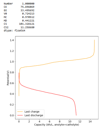
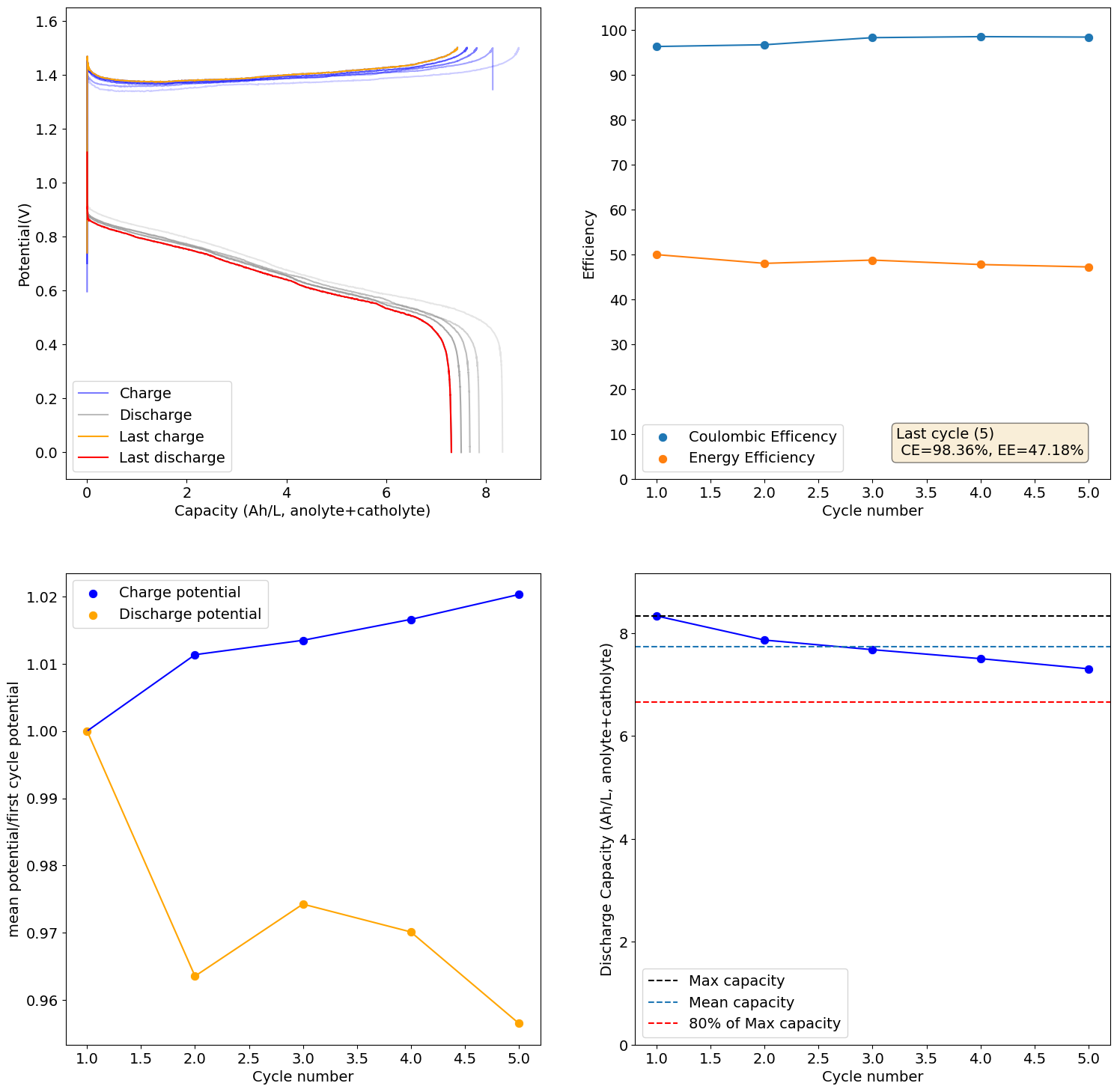
I recalibrated my mystat to ensure it is properly zeroed and got curves that make much more sense. This is for a new electrolyte I prepared with 1M Fe from FeCl2.2H2O, 2.5M CaCl2 and 1M NH4Cl (I added this as ammonium often helps prevent metal passivation). I also added 10mg/mL of citric acid, to serve as a buffering agent.
These are curves obtained at 0.5Ah/L charge/discharge at 10mA/cm2:
As you can see the potential has now stabilized and the final CE and EE values are quite good (for all Fe at least!). The discharge potential is also now +0.87V, which is in much better agreement with my CV values.
@gus Awesome news! Congratulations on your first successful test. Your results are really nice. The potentials are normal, when you charge to high SOC the potential will likely be around ~50mV higher at start of discharge. The resistance of your cell is actually quite low, so you did a really good job building everything 
What you observed is normal, when charging to very low SOC values (5-10%), the lack of full Zn stripping creates a metal film that continuously builds and increases the coulomb and energy efficiency of the device per cycle. Basically you have Zn that is not discharged that is more conductive and easier to plate onto and then strip from. If you continue you would see it stabilize somewhere around 80-85% CE and 70-75% EE. The color change you observe in the electrolytes is normal. The catholyte is normally red (gets black as you get more I3-) while the anolyte is normally transparent or slightly yellow due to the presence of I3- that leaks from the catholyte through the membrane (as the membrane is not selective).
Ideally on a fully discharged cell both electrolytes should go back to fully transparent, but since we have oxygen reacting with some iodide, this never happens.
About the pump speeds, I generally charge/discharge at around 30-35% of the total pump speed. When you cycle for a long time you will also notice fluid transfer from the anolyte to the catholyte. To avoid this, you can run the catholyte pump slower and the anolyte pump faster (see here https://www.sciencedirect.com/science/article/abs/pii/S138589472100098X). A ratio of 1:7 (catholyte:anolyte speed) was found in this paper to work best for this. I have never run it so fast, in my experience running the catholyte at 45% and the anolyte at 30% is usually enough of a difference to prevent most of the migration.
This is the result of charging the 1M Fe, 4.5M CaCl2, 1M NH4Cl cell to the Nernst limit (1.5V)
There is still some decay in capacity due to increases in resistance, although much slower. I will now charge this to 6.5Ah/L, see if it can cycle in a stable manner at that capacity.
It is incredibly exciting to see you guys reproducing the kit! We are really excited about completely independent third parties being able to just build and run this thing.
I also just got birchwood endplates for the first test of the large scale design. These are 1.8cm thick, so stiff enough to be able to seal the cell in theory. Since there is no chemical contact with the endplate, we shouldn't have any problem using this material. I will get brass current collectors next week - Xometry just shipped them to me - and will then proceed with the first test.
@sepi It doesn't, propylene glycol was also tested on the research paper that found triethyleneglycol worked. You need a very specific structure to stabilize the polyiodides.
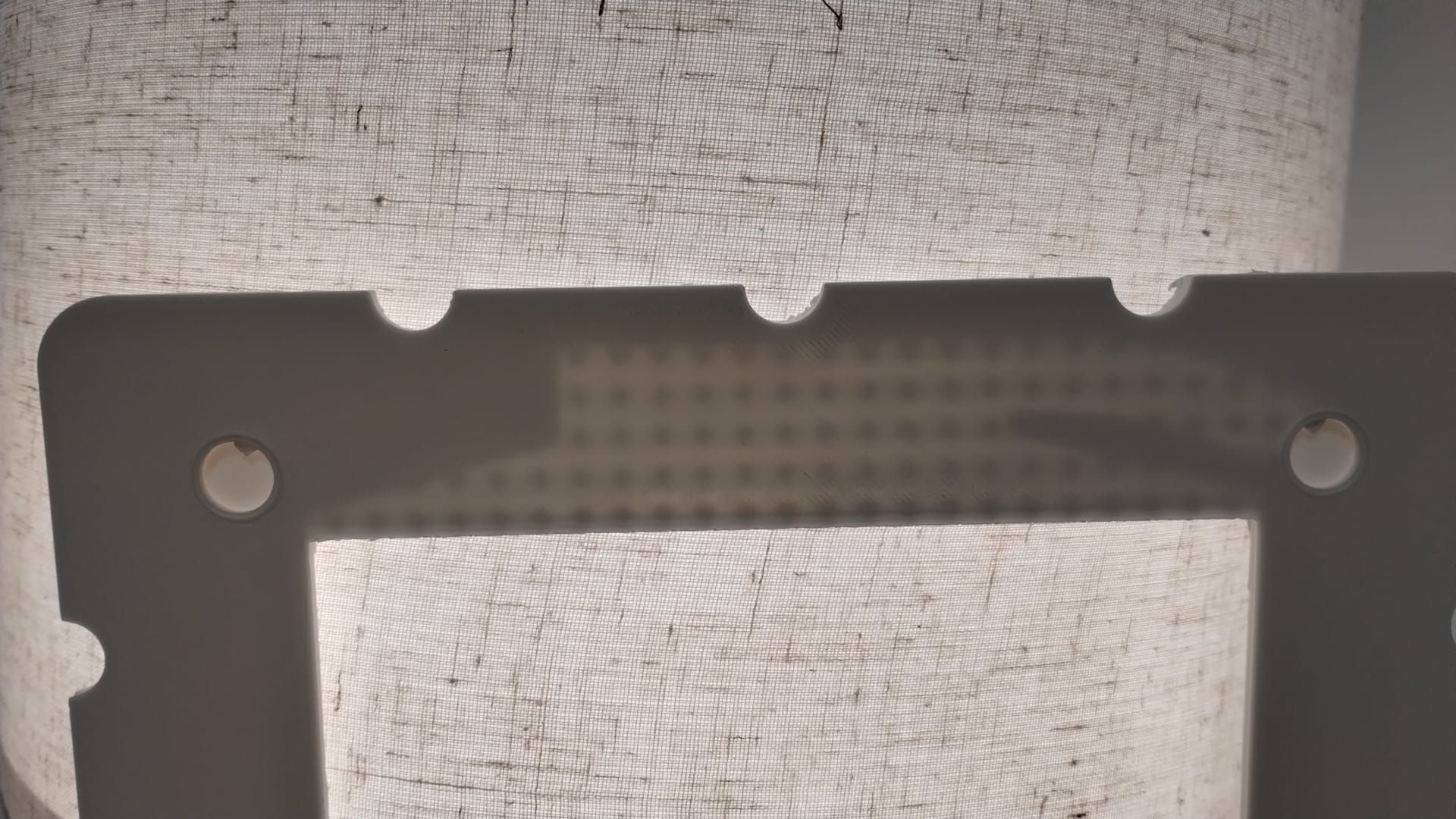
All flow frames are ready now. I'll have to wait a couple of weeks for some graphoil to cut the bipolar plate material that goes between the cells. Picture of the 6 finished flow frames below. I won't be running this with any active material, as I have no place to safely do so, I will just be testing for leaks to test the basics of the stacked design.
If ran with active material the expected voltage of this system with Zn-I would be ~3.6V and the current needed to charge it in a reasonable time would be around 3.5A. The system would produce around 12.6W, power capacity would be around 60Wh, would require around 1.5L of catholyte and 1.5L of anolyte. This would be enough capacity to run a raspberry pi for 12 hours.