Skip to content
  • Categories
  • Recent
  • Tags
  • Popular
  • Users
  • Groups
Skins
  • Light
  • Brite
  • Cerulean
  • Cosmo
  • Flatly
  • Journal
  • Litera
  • Lumen
  • Lux
  • Materia
  • Minty
  • Morph
  • Pulse
  • Sandstone
  • Simplex
  • Sketchy
  • Spacelab
  • United
  • Yeti
  • Zephyr
  • Dark
  • Cyborg
  • Darkly
  • Quartz
  • Slate
  • Solar
  • Superhero
  • Vapor

  • Default (No Skin)
  • No Skin
Collapse
Logo that says

Flow Battery Research Collective

G

gus

@gus
About
Posts
30
Topics
1
Shares
0
Groups
0
Followers
0
Following
0

Posts

Recent Best Controversial

  • Following your documentation – feedback & questions
    G gus

    @danielfp248 I always performed more cycles before starting 40 mA / 100 mAh charging (10 half-cycles at 20 mA / 10 mAh + 4–10 half-cycles at 30 mA / 10 mAh). The cell was also wet with demineralized water (leakage test). Could this also be the cause? I was also always using the membrane frame. Wouldn't the electrolyte leak through the paper membrane?

    @kirk Apart from solving the electrolyte leakage issue, does this "pulling-through configuration" improve the total capacity of the system in any other way? Also, I am wondering whether you are using the default membrane frame from the documentation (2 mm thick, right?) or a different one with another thickness and the 0.1 mm silicone gaskets.

    General Discussion

  • Following your documentation – feedback & questions
    G gus

    @danielfp248 Wow, that’s much more than I’ve ever been able to obtain. Did you do anything to the graphite felt or the paper membrane before using them? Did you use the default membrane frame from your documentation, or did you adjust the thickness to better fit three sheets of photo paper? What charge/discharge currents, capacities (mAh), and cycles (half-cycles) did you perform before achieving the result you posted? And what current did you use for the final charging of the cell - 40 mA or less? Are you planning to continue using pumps that generate a vacuum behind the cell, despite all the weak points of this solution?

    General Discussion

  • Following your documentation – feedback & questions
    G gus

    @danielfp248 Thanks. So I’ll wait for the results you can achieve with the same setup I’m using.

    Regarding the suction-based pump configuration - I’ve been thinking about it too. Generating underpressure behind the cell would likely remove leakage issues. However, it is a more energy-consuming solution, so it doesn’t seem suitable as a final approach for a large battery system. Also, with the pumps operating in suction mode, any sealing imperfections would likely result in air being drawn into the system...

    Thanks again for running the photopaper membrane tests - looking forward to the numbers.

    General Discussion

  • Following your documentation – feedback & questions
    G gus

    Oh, I didn’t realize the 166 Wh/L value was referenced only to the catholyte, so thanks @danielfp248 for pointing that out.

    In the meantime, it occurred to me that maybe the ambient temperature (10–15 °C) could be a cause. What do you think?

    Regarding electrolyte circulation: I use the same Kamoer KPK200 pumps, currently set to 30% on the catholyte side (just to confirm — that’s the electrolyte that turns red during operation, correct? ) and 45% on the anolyte side. I also ran the cell without using PP felt on either side.

    Thanks for all the practical advice. However, I’d like to understand if there were any additional factors or preparation steps not mentioned in the build instruction? For example: activating the graphite felt, using PP felt in any configuration, or modifying the photopaper membrane?

    I would like to make my cell and electrolyte work in the same “default” setup that you have already proven.

    Thanks again for your time — and also for the offer to share membrane samples. I think I will be interested in testing other membranes after making the cell work reliably with photopaper first.

    General Discussion

  • Following your documentation – feedback & questions
    G gus

    Hi everyone,
    Over the past few months I've started tests multiple times. In some cases, leaks appeared within the first 5 charge cycles when charging to 10 mAh at 20 mA. However, if the system was leak-free at the beginning, it would usually survive the subsequent charge cycles as well. Unfortunately, I have never managed to reach 100 mAh while charging at 40 mA, following the guidelines you provided.

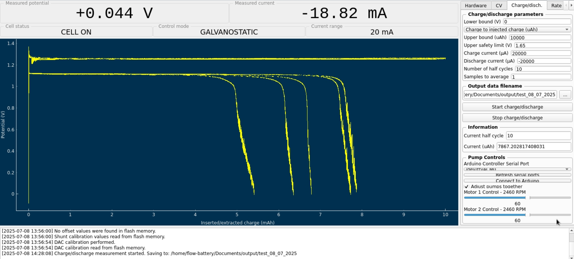
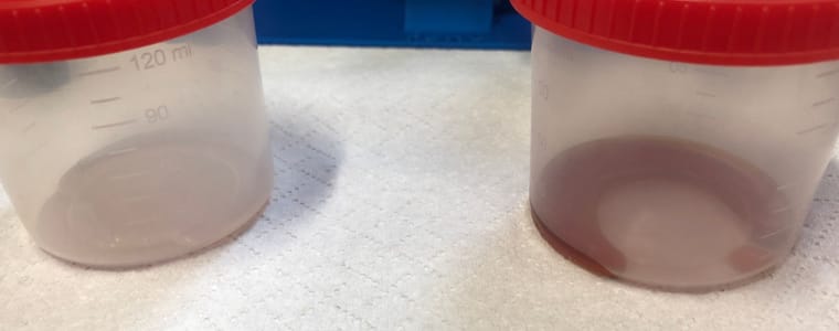
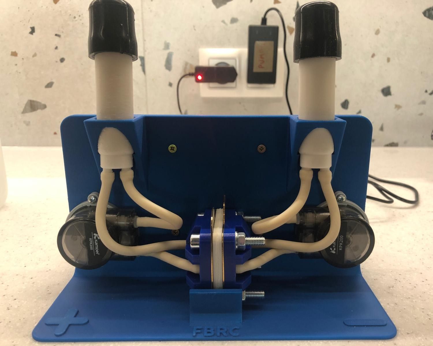
    Each time, the voltage reached 1.65 V much earlier than expected (on average around 40 mAh). Leaks occurred frequently (tubing burst, the cell lost its seal, and once the electrolyte even suddenly leaked from the tanks(!)). On the voltage plots, these leaks showed up as sudden spikes or unstable/uneven charging voltage values. I suspect that something was often getting clogged in the system, causing a rapid pressure increase. I measured that Kamoer KPK200 pumps can generate over 0.4 MPa (!) of pressure when the outlet is blocked.

    There were also attempts where I did not observe a visible leak — but even then, a one-off voltage disturbance still occurred. In those cases, the voltage began rising faster, and shortly after that it still hit 1.65 V, stopping the charge. My MyStat is calibrated, and I additionally verified the charging voltage with a multimeter to confirm it was definitely 1.65 V.

    For most of my tests I used a membrane made of 3 layers of photo paper, as suggested by @kirk . Recently, I also tested a 4-layer photo paper membrane. In that setup, the charging voltage was immediately about 0.1 V higher, and it also reached 1.65 V at just under 40 mAh, stopping the charge.

    I assume that in your setups you can repeatedly charge to 100 mAh at 40 mA without issues. And 100 mAh doesn’t seem like much when compared to the results in this publication https://www.nature.com/articles/ncomms7303 , where the authors reported 166.7 Wh/L. For an FBRC cell, that would correspond to roughly 1200 mAh, correct?

    Do you have any advice for me? Where could the root cause of my failures be?
    Am I definitely not supposed to use polypropylene felt on the catholyte side?
    Could there be an issue with the material quality I'm using (even though everything was purchased according to the Bill of Materials sources)?

    Pasting results from my latest run below — the 4-layer photo paper membrane test, charging current 40mA.
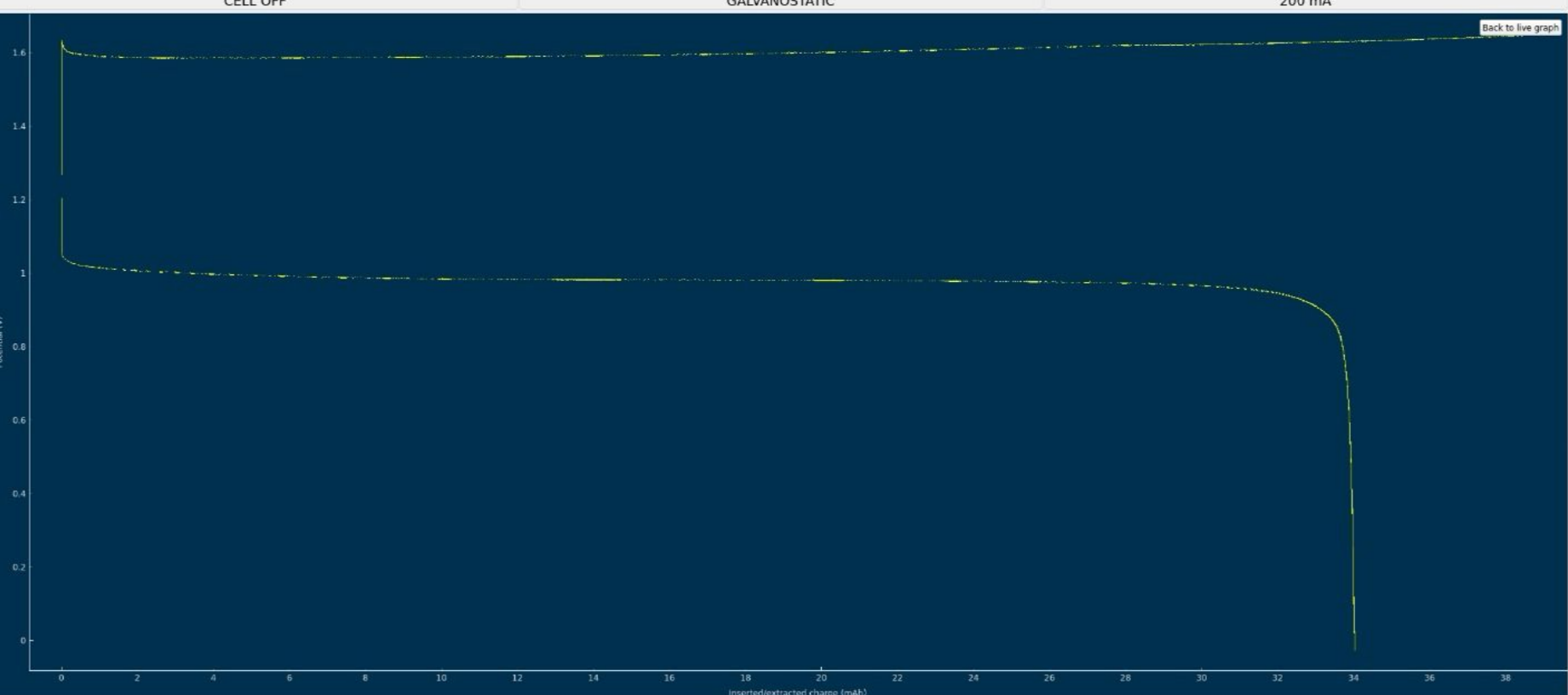
    image.png

    General Discussion

  • Following your documentation – feedback & questions
    G gus

    Hello everyone! It’s been a while 😊
    I’ve returned to testing the flow cell and even built a second one to check repeatability. I’m wondering what could cause such a large difference in performance between them. The second cell showed only 0.85 V during discharge (compared to 1.15 V for the first one).

    There was also a warning during the discharge of the first (better) cell:

    “The command b'RANGE 2' resulted in an unexpected response. The expected response was ‘OK’; the actual response was ‘WAIT’.”

    After closing this warning and restarting the charge/discharge cycles, the system no longer stopped charging the cell at 10 mAh as before. I manually stopped the cycle at 22 mAh.

    The cell was left in the workshop, and I was remotely connected from home to the Raspberry Pi controlling the pumps and Mystat. The next day, when I returned to the workshop, both tubes from the pumps had detached from the cell, and the electrolyte had spilled on the table.
    Do you have any idea what might have happened?

    I also wanted to ask whether you’ve tried different gasket materials—such as FKM (Viton) rubber or expanded PTFE (ePTFE)?

    General Discussion

  • Following your documentation – feedback & questions
    G gus

    @sepi Sorry for the late reply. I'm glad the first attempt was successful and that I’ve learned how it works! I believe flow batteries are the future - at least for stationary systems. So, what’s next? Maybe I’ll try designing my own small battery… 🙂

    General Discussion

  • Following your documentation – feedback & questions
    G gus

    @sepi , thanks for the kind words. @danielfp248, @kirk It is really cool that you have done and made this project available! Building and testing it personally is an experience much more valuable than just reading an article.
    I'll be honest — before the first test, I was a bit worried that a leak might suddenly appear.
    I'm also glad, @danielfp248 , that you confirmed the accuracy of my results.
    I'm looking forward to seeing your project develop! 🙂

    General Discussion

  • Following your documentation – feedback & questions
    G gus

    I’ve finally completed the first tests of the battery.

    @danielfp248, I used the parameters you suggested, but I had to enter one of the currents (either charge or discharge) with a negative sign. With each subsequent cycle, the efficiency improved (as shown below). Is this difference in capacity from cycle to cycle expected?

    first_test_gus.png

    I expected the program to automatically adjust the pump RPMs, but it turned out I had to set them manually. I'm not sure if the values I chose were appropriate.

    Now I understand why you mentioned that the connection combination didn’t make a difference 🙂
    However, I still have some doubts about the resulting voltage value—doesn’t it seem too low?

    Before turning on the pumps, I zeroed Mystat. I’ve just realized that it should also be calibrated with a 1.000 kOhm resistor.

    I used the tubing that came with the pumps. After completing five cycles, I emptied the electrolyte and rinsed the system several times with deionized water.

    Now that I know the system works, I’ll look for proper electrolyte-resistant tubing and continue with further testing.

    Here’s how the electrolyte’s color changed after just a few cycles:

    electrolyte_after_5_cycles.jpeg

    General Discussion

  • Following your documentation – feedback & questions
    G gus

    Ok, thank you @danielfp248 ! I know I'm probably being a pain, but I just wanted to be absolutely sure:) So this part is already solved.

    However, I have found out that mystat.py was not able to save results to a file.

    On the Raspberry Pi that I am using right now, I was unable to install PyQt5 in a virtual environment following your readme.txt and requirements.txt file. The problem is known and I have not found a working solution for the venv setup. As a workaround, I was using the default version of Python and libraries. This was probably causing the file saving issue.

    Happily, the script seems to be working on the Raspberry Pi's default system Python and libraries after changing the "choose_file" function to the following:

    def choose_file(file_entry_field, questionstring):
    """Open a file dialog and write the path of the selected file to a given entry field."""
    filedialog = QtWidgets.QFileDialog()
    # Get the tuple (filename, filter) and take only the filename
    filename, _ = filedialog.getSaveFileName(mainwidget, questionstring, "", "ASCII data (*.txt)",options=QtWidgets.QFileDialog.DontConfirmOverwrite)
    file_entry_field.setText(filename)

    I hope there will be no more incompatibility issues during battery testing 😊

    General Discussion

  • Following your documentation – feedback & questions
    G gus

    @danielfp248 Ok, thank you. So there is no need to assign one peristaltic pump to WE/SE and the other to CE/RE? Because if the electrodes are connected arbitrarily, this information will not be passed to mystat.py, right?

    Edit: I suppose that I should connect the WE/RE to the electrode associated with the positive (P) pump circuit, and the CE to the electrode associated with the negative (N) pump circuit.

    General Discussion

  • Following your documentation – feedback & questions
    G gus

    Another question before I start the test: I understand that I need to connect WE/SE to one electrode and CE/RE to the other. Does it matter which electrode is connected to which pair? Does the Mystat.py script differentiate between them?

    General Discussion

  • Following your documentation – feedback & questions
    G gus

    @danielfp248 said in Following your documentation – feedback & questions:

    After that you can then start going to high SOC values at 40000uA. I would recommend first cycling to 100mAh (set Upper bound to 100000uAh). Enclose the battery when cycling to higher SOC - you can put it inside a plastic tub - because leaks due to any problem will spray highly charged electrolyte, which, even if the volume is low, can be dangerous.

    Thank you for this advice. To be honest, I’m a little bit afraid of leaks that could damage the Arduino, above all. Do you propose covering just the cell, or the whole system? I’ve placed the system in an IKEA Samla box, and I can cover it, just making some holes for the cables. Do you recommend extra covering for the cell as well?

    General Discussion

  • Following your documentation – feedback & questions
    G gus

    @sepi, @danielfp248 thanks :), @danielfp248, I have an exact electrolyte from the documentation https://fbrc.codeberg.page/rfb-dev-kit/electrolyte.html .

    General Discussion

  • Following your documentation – feedback & questions
    G gus

    It's been a while, but I’ve just configured a Raspberry Pi and got the mystat.py script working alongside Mystat and the Arduino. It looks like the chemistry is ready as well. Could I ask you for some instructions on how to proceed with the test using the mystat.py script? There are multiple options available, and I want to make sure everything is set up correctly 🙂

    General Discussion

  • Following your documentation – feedback & questions
    G gus

    @kirk said in Following your documentation – feedback & questions:

    Could you share the file you modified? It looks like you added a big cylinder.

    I have send you an email,

    @kirk said in Following your documentation – feedback & questions:

    The program here * should * work on linux when run as root (in order to have proper USB access). You can control the pump speeds via the Arduino with the software, even without the MYSTAT connected (under the "charge/discharge" tab) (this will all hopefully be in a video soon!)

    Thank you. I am planning to use a Raspberry Pi for long-term tests. Are you using a Raspberry Pi too, or a PC?

    @kirk said in Following your documentation – feedback & questions:

    In the CAD files we have specified a 2D endplate (https://codeberg.org/FBRC/RFB-dev-kit/src/branch/main/CAD/exports/Metal Endplate.step), that could be laser cut or milled from aluminum. @danielfp@chemisting.com has received endplate versions of this in aluminum, the only catch is then you need insulating washers so as to not short them. Another rigid polymer could work too.

    Thank you. For now, if there are no leaks during the long-term tests, I will not change these endplates.

    And also, I wanted to ask you about the current collector's material – is brass a better option than pure copper? What was the criterion for the material type and thickness selection?

    General Discussion

  • Following your documentation – feedback & questions
    G gus

    Thank you @kirk . Yes, I had already understood it from your previous message.

    I’ve finished the assembly and performed a leak test using demineralised water. The first attempt failed due to leaks in both reservoirs (see photo). After that, I made a small design change and increased the 3D printer’s flow rate for the infill. The new reservoirs seem fine now.
    Did you encounter this problem too? How did you solve it?

    reservoir_leak.jpg

    test_demi.jpg

    The cell itself doesn’t leak. I used a torque of 3 Nm for now, but it already looks slightly distorted. Have you considered using more bolts?

    I also wanted to ask: is silicone resistant to this type of chemistry? Since it’s used for gaskets, maybe silicone tubing could be used as well?

    Regarding the Arduino program: it seems there are four defined pins — In1 (pin 9), In2 (pin 8), In3 (pin 7), and In4 (pin 6) — but they don't appear to serve any purpose.

    As for the main Python program — should it work with no issues once the Arduino and MYSTAT are connected to the computer?

    General Discussion

  • Following your documentation – feedback & questions
    G gus

    While assembling the flow cell, I noticed that the manual doesn't mention anything about the Membrane Frame. I also have doubts whether the Membrane Frame model provided on the website isn't too thin (0.8 mm) to ensure a proper seal when using 4 membranes made from 230g/m² matte photo paper. Each membrane, according to my measurements, is 0.3 mm thick — which means the total thickness is 0.4 mm greater than the Membrane Frame's thickness. I also used 0.1 mm gaskets (as specified in the Bill of Materials), so such a large difference in thickness is unlikely to be compensated.
    @kirk, do I need a thicker Membrane Frame or thicker inner gaskets?

    General Discussion

  • Choice of plastic
    G gus

    Thank you for the comprehensive answer — I think you've convinced me to go with PP 😊

    General Discussion
  • Login

  • Don't have an account? Register

  • Login or register to search.
Powered by NodeBB Contributors
  • First post
    Last post
0
  • Categories
  • Recent
  • Tags
  • Popular
  • Users
  • Groups