Skip to content

World

Topics from outside of this forum. Views and opinions represented here may not reflect those of this forum and its members.

A world of content at your fingertips…

Think of this as your global discovery feed. It brings together interesting discussions from across the web and other communities, all in one place.

While you can browse what's trending now, the best way to use this feed is to make it your own. By creating an account, you can follow specific creators and topics to filter out the noise and see only what matters to you.

Ready to dive in? Create an account to start following others, get notified when people reply to you, and save your favorite finds.

Register Login
  • S

    Hello, I am in the process of putting the benchtop flow battery together. It is a bit difficult to get the exact materials.
    My knowledge of plastic and its chemistry is somewhat limited.

    I'm interested in why the specific plastics were used and which ones could be used as substitutes.
    What criteria need to be considered?
    What has already been tested?
    What else could be tested?


    @gus @SamAuc ABS may work with an all-copper chemistry!
  • kirkK

    Thread to keep track of our zinc-iron develepment. This is quite preliminary, based roughly off of Savinell's work.

    Zinc is preferentially plated on the negative side, even though the potential for doing so is more negative than iron, which is present in solution.

    SOC ranges tested have been quite minimal however.

    Some of @danielfp@chemisting.com's initial testing is here:

    0b0de370-5f70-4437-9953-144d46f8f37f-image.png

    From Daniel:

    This is 2M FeCl2, 3M ZnCl2, 2M Glycine. At 20mA/cm2. Felt on both sides, daramic membrane. The pH of this is 3.2, but the CE is quite high so H2 generation must be quite low.

    Running to higher capacities you get dendrites quite quickly. I am trying 2M FeCl2, 3M ZnCl2, 2M Glycine with 1M NH4Cl with the nonconductive felt on the anode.

    I'm also going to change to the fancy pumps with PTFE tubing after this run.


  • O

    Hi everyone!

    I'm currently working for professor Sanli Faez in making a website, where people are guided through the construction of the rfb dev kit, as a multi-day project. The idea is to give people a general idea of how batteries work, the project goals and redirecting them to the fbrc build instruction for the actual build. The first version of the site has just been uploaded. However, I haven't done anything like this before, so I was wondering if some of you would like to take a look at it and send me some feedback. All feedback is welcome!

    The site link is given below:

    https://fair-battery-project.netlify.app/

    Thank you in advanced!

    With kind regards,

    Otmar van Benthem.


    Hi Otmar! I think it would be helpful to see a rough schedule of the workshop and time allocations per topic/activity - then it would be easier to give feedback for the site, based on specifics of the activity the site is meant to complement!
  • kirkK

    Cloning the https://codeberg.org/FBRC/RFB-dev-kit repository, opening the assembly in FreeCAD, fixing part of it, then pushing the changes with VSCodium. As part of the Flow Battery Research Collective project at https://fbrc.dev 0:00 Cloning repository 3:29 Opening assembly file 4:09 Fixing the cell assembly 20:20 Pushing changes to repository
  • O

    Hi,

    I'm Otmar, a first year Experimental Physics master student based in Utrecht.
    I'll be helping professor Faez in making a website with instructions so people can do a FAIR-battery day project. I'm very excited to join the project!

    With kind regard,

    Otmar van Benthem.


    Hi Otmar, welcome to FBRC and the project, looking forward to working with you!
  • kirkK

    I bought two of these to use for the large-format cell and stack. I'm in the process of setting them up to pump water in a loop, just to make sure they work, and to see if I can control their speed with an AC dimmer.

    Centrifugal pump with spec sheet

    Backside of centrifugal pump

    Disassembled centrifugal pump

    I have two dimmers that are basically this:

    Image of black PCV with aluminum heatsink and connectors, labeled "AC DIMMER MODULE"
    https://robotdyn.com/ac-light-dimmer-module-1-channel-3-3v-5v-logic-ac-50-60hz-220v-110v.html

    I have an Arduino UNO handy, from the development kit. Seems I could use this library or similar one (https://github.com/fabianoriccardi/dimmable-light/tree/main) to control them. For example with this code:https://github.com/fabianoriccardi/dimmable-light/blob/main/examples/2_dimmable_lights/2_dimmable_lights.ino

    I would use one zero crossing detection on the UNO interrupt pin and then control the two dimmers/motors with two output pins going to the dimmer modules.

    Does this seem like a reasonable approach? This is not my field of expertise. Tagging @H4K1


    @kirk said in How should we control the centrifugal pumps? TRIAC/thyristor etc? Need help from controls/electrical people: It seems to work! At least enough for testing purposes. Here is a video: https://spectra.video/w/8xipM8aXnBkDXnu4kkRpqT Here is the code for this test: https://codeberg.org/FBRC/RFB-test-cell/src/commit/d10834bc7dd67736e708c9a33832a5602ab3ca28/firmware/FlowrateRampTest.ino
  • danielfp@chemisting.comD

    Our goal at the Flow Battery Research Collective (FBRC) during the past year has been to develop and manufacture a flow battery kit that can be used to study flow batteries at a small scale in a low cost yet reproducible manner. Today I want to discuss all the problems we have found when attempting long term cycling in both versions of our kit and how we have addressed them so far.

    Long term cycling results with the first version of our kit. Around 5 days of cycling.

    Our first kit design – which you can see above – was able to do long term cycling of an electrolyte composed of Zinc Chloride (1m) and Potassium Iodide (2m) in a potassium acetate/acetic acid buffer (pH=5.2). We were able to obtain capacities higher than 10Ah/L (on total volume of electrolyte — note previous values on this blog were based on catholyte only) without much capacity fade at the 25 cycle range. I didn’t try longer term cycling because of issues with pumps getting damaged by the tubing I was using leaking iodide (see how orange the right pump above looks, that’s not supposed to happen). At this point we were also testing several types of tubing, reason why you can see different colors of tubing in the setup.

    However, this design had two big issues. The first is that the polypropylene bodies were getting over compressed at the top and under compressed at the center, so after a single long term cycling event (cell cycling for 5 days), the cell would never seal well again after being opened due to warping of the body. This made this design completely unfeasible and forced us to accelerate the development of v2.

    Long term cycling results of second version of our kit. Cycling was also around 5 days.

    The second cell design – showed in the second image above – has a square design with even compression and complete isolation of the cell body from the electrolyte by using a sealed polypropylene flow frame (you can read more about it in the FBRC website). However, despite using the exact same electrolyte and membrane, this design has been showing some increasing decay of the electrolyte as a function of time. The cycled capacity is a bit lower and after 28 cycles the testing had to be stopped due to obvious deterioration of the charging potential.

    Flow batteries using microporous membranes can suffer from significant issues related to hydraulic pressure differences between anolyte and catholyte. As the battery is cycled, there is net water transfer between both sides and this can lead to the accumulation of polyiodide species in a Zn-I flow battery. This deteriorates the charging potential and reduces the SOC of the battery. You can ready more about this decay mechanism in this paper. When my testing was done, there was indeed an almost 50% less fluid in the anolyte vs the catholyte side, interestingly the completely opposite effect when compared to the paper. Changing the supporting electrolyte concentration or Zn salt used – to make the water changes less extreme – or adjusting electrolyte flow rates, can help eliminate these volume balance issues.

    New flow frame design for the second version of our kit. You can see the flow channel has been colored red by the catholyte. The flow frame was 3d printed. Since 3d printing leaves some porosity (even at 100% infill) you can see some coloring even away from the flow channel.

    There are however other problems with the current tests. The first is that the chemistry is not stable to oxygen – both due to iodide and zinc reactivity – so working under atmospheric conditions without any inert gas purging of the electrolyte has likely made my tests more unstable, due to Zinc passivation and pH instabilities caused by the reactions of iodide with oxygen. Since the new flow frames are 3d printed – therefore not 100% free of pores – they might be letting more oxygen in, which might also be why the system is more unstable than v1 in this regard. Getting flow frames manufactured through polypropylene sintering or injection molding could get rid of this issue.

    Another issue – shown below – is the use of graphite foil (grafoil) as our electrode material. Although grafoil does the job fine, it does seem to be porous to iodine, which crosses it and reacts with the underlying copper, increasing series resistance and creating a protuberance on the copper plate (which is readily visible in the image after long term cycling). I scratched the grafoil to then reveal a white powder, which is copper iodide, leading to a further loss of capacity. This problem could be solved by using a proper bipolar plate material or by sealing the grafoil in some manner. Thicker grafoil could also be enough to ameliorate the problem.

    Catholyte side graphite foil, 0.5mm, after 5 days of cycling. You can see a bump in the foil caused by buildup of copper iodide material below the electrode.
    A high capacity short cycle result using a Zn-I electrolyte. This is using total volume of electrolyte, so a capacity that would be in line with current Vanadium batteries.

    I also want to note that we have achieved much higher capacities – see above – although not in long term cycling, as these higher capacities generate much more concentrated electrolytes that have significant problems (such as the precipitation of insoluble solid elemental iodine and the corrosion of the pumps and copper current collectors).

    As you can see, getting long term cycling results is not easy. There are many hurdles to overcome to be able to provide a kit that is able to cycle a chemistry like Zn-I long term, without any problems, in a reproducible manner. All these hurdles can be overcome though – as there are plenty of examples of people cycling these batteries long term – so it is a matter of arriving at a proper combination of materials and chemistry. Our work continues! Thanks a lot for all your support.

    This flow battery kit work is being funded by the Financed by Nlnet’s NGI0 Entrust Fund. We are also collaborating with the FAIR Battery project.


    Nice work, Daniel. I am thinking of plumbing solutions to the imbalance issue: From A review of all-vanadium redox flow battery durability: After studying the capacity fade for mixed acid electrolyte, UET [154] found that, during long‐term operation, the ratio of catholyte and anolyte concentration remained constant: 1.3:1. Based on this finding, they designed an overflow system with different volume (volume ratio: 1.3:1) anolyte and catholyte tanks, in which the volume ratio and total vanadium were kept constant. With the new design, the VRFB achieved long term capacity and efficiency stability. However, this design is only valid for the mixed acid electrolyte system. Recently, Wang et al [152] developed an electrolyte reflow method to solve the electrolyte imbalance issue for the sulfuric acidvanadium electrolyte system. Figure 10 shows the schematic of their method; without reflow, eventually all of the anolyte will move to the catholyte tank, while with reflow, the anolyte tank will always contain some electrolyte. Similar to the UET method, the volume ratio of catholyte to anolyte is a key parameter affecting the capacity stability and is highly dependent on the operating current density. Cycle life and total capacity were all improved with the reflow method. There is also Capacity balancing for vanadium redox flow batteries through electrolyte overflow but it was retracted - they think they accidentally had a pinhole in their membrane for the test. But they did build a real overflow system: [image: 1739741378711-aceadcdb-fb4d-4387-b6c6-9b95a79cc192-image.png]
  • kirkK

    Micro-update

    Here are some pics of what we're up to in the hackerspace! Currently rebuilding the kit and setting up a test system for these centrifugal pumps, which are magnetically driven and all-polypropylene (no rotating seal). Currently setting up the power electronics to try to do speed/flowrate control/ramping.

    Pic of a flow battery development kit with a red/white cell, white peristaltic pumps and reservoirs, and a purple jig holding it together, all FDM-printed

    Centrifugal pump with spec sheet

    Backside of centrifugal pump

    Disassembled centrifugal pump


    That's great! Do you have a link to one or know where we could procure one to test?
  • H

    Okay, so we would have 3 main things to do in our CI:

    1. Generate STEP files from FreeCAD
    2. Generate PDF files from KiCad
    3. Unittest (in the future) and generate binary/hex file

    As from my point of view all of three sections should be separated in different repos and combined using git submodules, though there are few problems I see, mostly in CAD:

    1. CI/CD must know from which input files generate output files - as for now they are kind of mixed in main CAD folder, so my proposition is to create separate folder for:
      1.1 3D_printed parts, as these need to be converted from *.FCStd into *.step
      1.2. 2D drawings parts, like Current Collector Drawing or Gasket Drawings which needs to be translated from *.FCStd into *.pdf
      1.3. Renders which would require rendering whole assemblies - those could be placed in Assembly folder

    We would end up with structure of:

    .
    ├── 2D_drawings
    ├── 3D_print
    └── Assembly
    
    1. Electronics is pretty simple, as there will be only KiCAD project, maybe the some kind of electronical/electrical calculations, though I think we are far from it now

    2. Similar with Firmware, there would be simply two folders: src and tests, but that is also a next step

    I would love to hear other opinions, my idea is to create CI/CD as simple as possible, due to fact that I understand that many ppl who would like to contribute with CAD files might be not familiar with any CI/CD, and for that I came up with that folder idea


    Stephen Hawes of Opulo has compiled some of their tools here: https://midscale.io/docs The AutoBOM one seems to be based on those workflows above and looks pretty interesting
  • B

    New member here. 😄

    I'm a Scottish engineer based in London.

    I'm a member of London Hackspace, and a few of us have been talking about working together assembling a dev-kit. With the tools that we have available, we would be able to work on designs with a larger form-factor... 😄


    I came across this project via Mastodon, and just finished watching the FOSDEM 2025 talk. 😄


    One of the problems you mentioned during the talk, was the materials used in the components, being reactive with the liquids.

    When you mentioned the pump failure due to this, i recalled this instructable for a 3d-printed water pump:

    https://www.instructables.com/3D-Printed-Powerful-Water-Pump-That-Is-Portable/

    Whether this design of pump has the optimum flows for the battery system is a separate question, but as it's manufacturable from a standard electric motor, and printable components.

    As they are printable, they can be made using your choice of printable materials, so that would avoid some of the problems you have already found. 😄

    Looking forward to trying these out. 😄


    Reading the posts about the different pump designs, it makes more sense. More background reading to do. TY
  • kirkK

    Importing a previous discussion from our old forum:


    kirk 1 September 23, 2024, 2:05pm

    For example, for residential storage applications:
    • 1 kW / 10 kWh
    • 70% system roundtrip efficiency including balance-of-plant
    • Chemical safety risk no greater than an equivalently-sized lead-acid battery bank
    Determining this ahead of time will help us chart an efficient path to get there, and
    hearing from real-world potential users will inform our R&D plans!
    What applications would you use a flow battery for, and what performance metrics
    would you desire?


    Sanli 2 September 25, 2024, 6:56am

    I think 70% is a good target, but for the mid-term. The existing commercial RFBs also
    don’t provide 70% and the low hanging improvements are in the system level (tanks,
    pumps, etc) before dealing with stack and electrolyte.
    As for the safety, it would be good to look at the existing standards for volume of acid
    beyond with a separate compartment is needed, I think it is about 250 litres, but I
    might be mistaken.


    kirk 3 September 25, 2024, 7:28am

    Good point about the secondary containment requirements for the liquid. This
    regulation probably differs around the world but would be good to look into. There
    are double-walled plastic tanks that count as secondary containment, but these are
    probably harder to get. For our first iteration it would make sense to pick a volume
    that is more manageable. Putting a big drip tray under the whole setup would be
    sensible too.


    Dogpoo 4 October 7, 2024, 2:20am

    Maybe want to be thinking about insulation, or even the option of a heating element
    if potentially users are going to stores the system somewhere like a utility room,
    cellar or garage where temperature can vary.


    kirk 5 October 13, 2024, 9:02am

    I’m not sure at which temperature you’d need insulation. The battery will self-heat to
    some degree during operation.
    Also, we will likely have an ambient temperature sensor and/or electrolyte temp
    sensor in a real system. The concentrated electrolyte should lower the freezing point
    of the electrolyte below that of water, but we’d have to do real tests with an
    environmental chamber or similar to really understand the viable temperature
    window.


    Dogpoo 6 October 13, 2024, 9:26am

    Good. Etc etc etc and so on and so forth. 20 characters.


    julianstirling 7 November 11, 2024, 2:45pm

    Secondary containment will be a “fun” thing to try to enforce for the open project as
    others start to experiment. I have found in the past that seemingly unneeded things
    often get ignored. Lots of caution messages explaining the need for secondary
    containment probably go a long way towards this.


    kirk 8 November 12, 2024, 8:36am

    Yes, good point, we will need to have lots of caution messages all around the
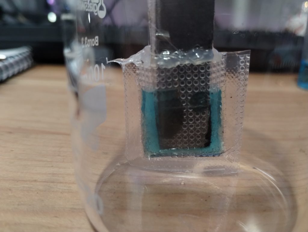
    documentation. For R&D purposes, we want people to be able to conduct tests using a minimum amount of materials, but there are always chemical risks no matter the
    quantity. For our benchtop system, the volumes are so low (around 10 mL total) that
    it shouldn’t be an issue, but for stack testing, we’ll have to spec an option, the more
    affordable the more likely people are to use it. And add some images and warnings of
    examples of chemical accidents where lack of secondary containment caused issues.


    julianstirling 9 November 12, 2024, 9:14am

    Yeah. I have taken a quick look through he docs I see there are quite a few.
    While it wasn’t safety related, we used to find for OpenFlexure everyone ignored on
    the printing page that the optics module should be printed in black. This changed
    when we started both explaining why and adding it to the checks:
    96dc0668-ddbd-4f52-8a19-dafb6466aea2-image.png
    then when you come to assemble it:
    92c48bbc-ba32-4636-b963-310956769714-image.png
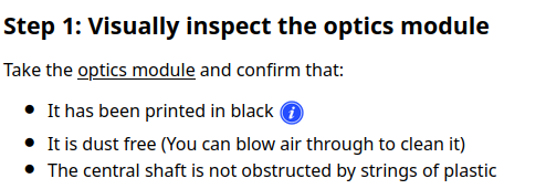
    It seems that the short bullet point sentences really helped people not miss what used
    to be in longer form text. The information symbol link to more detail.
    Dozuki had a really nice presentation about how to do documentation that really
    helped me. I’ll see if I can dig it out. Or if not remember the key messages.


    pinecone 10 January 27, 2025, 8:15pm

    What applications would you use a flow battery for, and what performance metrics would you desire?

    I’m thinking about intra-day arbitrage of market-priced electricity. The ratio of
    average consumed price to lowest daily price (night) is consistently about 10x or
    more here, so there is some potential to save money by time-shifting consumption.
    Do you have a cost estimate for a 1 kW / 10 kWh system (like above)? This would be
    more than enough to shave off the price peaks for a single household.


    kirk 11 January 29, 2025, 11:44pm

    Welcome to FBRC, @pinecone !
    I don’t have a straight-up answer for you right now. We don’t have a cost model or
    estimate yet but we would like to and will have to build one in time. I did some basic
    cost modeling in the past but for different chemistries/systems. It wouldn’t be too
    hard to have a simple spreadsheet for back-of-the-envelope style calculations.
    Daniel posted on another forum some basic calcs for a larger system that someone
    had asked about: https://diysolarforum.com/threads/my-adventures-building-a-diy-zn-i-flow-battery.69145/post-873727

    My adventures building a DIY Zn/I flow battery | DIY Solar
    Power Forum
    Quoting him here:
    DIYrich said:
    What is the usable energy of 30,000 litres?
    What is the cost of 30,000 litres?
    I’m wondering if it can be used for shifting summer production to winter
    usage.
    15,000 catholye + 15,000 anolyte at 35Ah/L would give you 525kAh which at a
    mean discharge voltage of 1.23V would give you 645 kWh, this is 0.645MWh, so
    very massive system. At 1mL per cm2 of electrode area you would also need to
    have 1500 m2 of electrode area, which at a standard 25cmx25cm per cell would
    imply having at least 24,000 cells. This is a massive system. Probably a couple of
    containers filled with stacks of cells to process what is literally a pool of
    electrolyte. Since the energy efficiency is 70-75%, you will need to put at least
    0.86MWh in to get that 0.645MWh out.
    At bulk prices of:
    ZnCl2 - 1700 USD/ton
    4 of 6
    KI - 2900 USD/ton
    NH4Cl - 450 USD/ton
    For 30,000L you would need 8.17 tons of ZnCl2, 3.20 tons of NH4Cl and 19.9 tons
    of KI. The total cost of the salts would be 32.1K USD.
    The above doesn’t include pumps, tank costs or cell costs. Note that since no ion
    selective membranes are used, this is going to be significantly lower cost
    compared with a Vanadium based system. Big systems have significant additional
    issues - for example pumping efficiency becomes a huge concern - so I’ll have
    clearer costs for you once we implement the first 25x25cm cells.
    We are however FAR from anything at this scale. Right now we are focusing on
    the small scale. Once everything is optimized the costs for larger scales might also
    drop further. Hopefully significant improvements in the energy density are still
    possible since the solubility does allow for much higher densities.
    Zinc-iodide isn’t the cheapest possible chemistry, but it’s working decently as a
    starting point.

    Daniel estimated 32.1K USD for 645 kWh of usable energy, so scaling that to 10 kWh
    is about $498 in chemical cost. The cost related to the 1 kW power component, the
    stack, requires more involved calculations, but there’s nothing particularly expensive
    component-wise in the stack (like platinum or gold…)—if you’re not using an
    expensive membrane. It’s mostly plastic and graphite (in various forms) with two
    copper plates and some tie rods, but the design and control of it is very important,
    which is what we’re focusing on now.
    Peak-shaving and intra-day arbitrage seem like great opportunities for RFBs though,
    that is definitely something we’d like to eventually see happen!


    pinecone 12 January 30, 2025, 9:08am

    Thanks for the info. The chemicals are surprisingly expensive.
    My very rough estimate of the break-even cost for a 10 kWh peak shaving system is
    about 1000 EUR, which does not leave much for the rest of the hardware after
    chemicals, even when allowing for DIY construction, 3D printed parts etc.
    This is a cool project though, best of luck!


    kirk 13 January 30, 2025, 10:51pm

    Thank you! And yeah, we are trying to develop a functional system, but it won’t be
    economically competitive as a DIY build for quantity=1—there would have to be a
    group buy or a business set up to buy chemicals in bulk, flow frames injection
    molded, etc. This project is for the R&D to get to a viable system, if we get to a
    functional system the idea is the project output’s are licensed for commercial use,
    and a real business could make it more affordable at scale.
    A kit build may be possible if there was a supplier for some of the specialty
    components or similar.


  • danielfp@chemisting.comD

    On my last post I wrote about the potential of using Fe/Mn in acidic solution to create an Fe/Mn flow battery. I cited a paper published a few years ago which shows that you can achieve reversible Mn3+ chemistry in a solution of sulfuric acid and hydrochloric acid, I then proceeded to confirm this reversibility using cyclic voltammetry of Mn2+ solutions in hydrochloric acid.

    However, it quickly became clear from analysis of the paper that this was only at very low capacities. This is because Mn3+ becomes unstable as its concentration increases in solutions, turning into MnO2 and Mn2+.

    A 0.5M Fe-DTPA + 0.5M Mn-EDTA solution in an acetate buffer (prepared with 100mL of 8% acetic acid + 10g of potassium acetate)

    Given the very low volumetric densities that can be achieved with the acid setup, there’s no option but to revisit the use of more stable and reversible forms of manganese. The best candidate seems to be Mn-EDTA. This complex has already been shown to work in flow batteries at the 0.5M-1.0M range (see here).

    I had already thought about using this complex and wrote several posts about its potential use in combination with Fe-EDTA or Fe-EDDHA (see here). However, there is a big problem with the pH compatibility of the Mn-EDTA with the Fe-EDTA or Fe-EDDHA. The issue being that Mn3+-EDTA is only stable under acidic pH conditions, where the solubility of both Fe-EDTA and Fe-EDDHA is limited to around 0.1M. These chelates are only highly soluble under basic pH conditions, which are fully incompatible with Mn-EDTA.

    CV of the solution shown in the first image. The half-wave potentials for both reactions are -0.11V and 0.61V, both Vs Ag/AgCl. The above CV was done with a scan rate of 10mV/s.

    The question is whether there is any easily accessible Fe chelate that is both compatible with Mn-EDTA in solution (so that we can create a symmetric electrolyte) and that can create soluble solutions at >0.5M concentrations in a pH ~5-6 buffer. Note that I need both chelates to be dissolved at >0.5M at the same time since I want the electrolyte to be symmetric so that it can work using a microporous membrane.

    The answer is Fe-DTPA. This chelate is highly soluble at acidic pH values and – best of all – it is soluble enough to actually be in >0.5M solution in the presence of Mn-EDTA at this high concentration. Above you can see a picture of the Fe-DTPA+Mn-EDTA solution. The solution also contains an acetate buffer, which should ensure pH stability on charge/discharge, which should prevent degradation of the Mn-EDTA.

    The second image shows a CV of the Fe-EDTA/Mn-EDTA buffered solution, showing that both the Fe and Mn electrochemical reactions are reversible. The half wave potentials are -0.11V and 0.61V, giving us an expected potential for the flow battery of +720mV. This is close to what I had measured before for Fe-EDTA/Mn-EDTA. This proves that the DTPA does not change the electrochemical characteristics of the system very much. The above test also confirms there acetate buffer is stable to the generated Mn3+-EDTA.

    The next step is to build a flow battery using the above solution and see what performance characteristics we can get. With the current solutions this system will be limited to around 8-9Wh/L. However I haven’t tested the solubility limits of the chelates in this buffer.


    Excited to try this in the dev kit one day... Though you mentioned that Mn(III)-EDTA might cause some trouble
  • H

    Idk if it is the best place to post, tho I did not want to do this in Codeberg, as to avoid unecessary text in development process

    So I would love to contribute into FBRC, I can help you with electronics, as well as firmware development, especially if you would like to develop more standalone device, in C/C++ or Rust (preferable, it just safer :P). I can also help to define/write unittests for the firmware

    Also my proposition is to create a [matrix] room to create a instant messaging possibility


    @H4K1 no need to build the flow battery and test chemistry to help the project out! You can also build and test just with water, especially the larger cell we'll build. But if you can do CI/CD and firmware now then that's great! You'd be the only one on the project now with those capabilities, so a huge bonus. It will help make a framework that we'll benefit from as the project advances and hopefully save us some time as we improve and develop, so we can focus on what we're all best at and enjoy!
  • kirkK

    The Flow Battery Research Collective is excited to present at FOSDEM this weekend! Come see us in-person or online.

    Details are all here.

    Track: Energy: Accelerating the Transition through Open Source
    Room: H.2214
    Day: Sunday
    Start: 10:55 (Brussels)
    End: 11:15
    Video only: h2214
    Chat: Join the conversation!

    Daniel and Josh will be presenting on our work. Looking forward to connecting with the many cool projects in our devroom and others, as well as hopefully meeting with other @nlnet@nlnet.nl and @ngizero@mastodon.xyz projects!

    Exploded view of a flow battery test cell

    Assembled test cell in a jig

    @fosdem@fosstodon.org


    Our talk is now viewable on PeerTube here: https://spectra.video/w/6BddEiwBqRMHSbC9qBLBz9
  • tserong@ourobengr.comT

    Still Going With The Flow

    It’s time for a review of the second year of operation of our Redflow ZCell battery and Victron Energy inverter/charger system. To understand what follows it will help to read the earlier posts in this series:

    Go With The Flow (what all the pieces are, what they do, some teething problems)

    Hack Week 21: Keeping the Battery Full (an experiment in working around the limitations of a single ZCell)

    TANSTAAFL (review/analysis of the first year of operation)

    In case ~12,000 words of background reading seem daunting, I’ll try to summarise the most important details here:

    We have a 5.94kW solar array hooked up to a Victron MPPT RS solar charge controller, two Victron 5kW Multi-Plus II inverter/chargers, a Victron Cerbo GX console, and a single 10kWh Redflow ZCell battery. It works really well. We’re using most of our generated power locally, and it’s enabled us to blissfully coast through several grid power outages and various other minor glitches. The Victron gear and the ZCell were installed by Lifestyle Electrical Services.

    Redflow batteries are excellent because you can 100% cycle them every day, and they aren’t a giant lump of lithium strapped to your house that’s impossible to put out if it bursts into flames. The catch is that they need to undergo periodic maintenance where they are completely discharged for a few hours at least every three days. If you have more than one, that’s fine because the maintenance cycles interleave (it’s all automatic). If you only have one, you can’t survive grid outages if you’re in a maintenance period, and you can’t ordinarily use the Cerbo’s Minimum State of Charge (MinSoC) setting to perpetually keep a small charge in the battery in case of emergencies. As we still only have one battery, I’ve spent a fair bit of time experimenting to mitigate this as much as I can.

    The system itself requires a certain amount of power to run. Think of the pumps and fans in the battery, and the power used directly by the inverters and the console. On top of that a certain amount of power is simply lost to AC/DC conversion and charge/discharge inefficiencies. That’s power that comes into your house from the grid and from the sun that your loads, i.e. the things you care about running, don’t get to use. This is true of all solar PV and battery storage systems to a greater or lesser degree, but it’s not something that people always think about.

    With the background out of the way we can get on to the fun stuff, including a roof replacement, an unexpected fault after a power outage followed by some mains switchboard rewiring, a small electrolyte leak, further hackery to keep a bit of charge in the battery most of the time, and finally some numbers.

    […]


    @kirk I hadn't spotted this years update to @tserong system - Thanks for the pointer! Bummer about redflow going under. We've gone for the riskier lump of lithium strapped to the outside of the house (Just as well Snug never has bushfi...oh). Can confirm that the #tasnetworks cablepi objects when we're off-grid. Reminds me I need to chase installer as our grid-tied inverter (on the essential load side) rightly objects to the 55.1Hz Sonnen runs at when in island mode - Want to decrease this.
  • kirkK

    Hello, World Fediverse!

    We are migrating our forum hosting to @nodebb@fosstodon.org to try to engage with the fediverse more broadly.

    You should be able to reply to this topic from your ActivityPub-enabled client, upvote ("favorite" on Mastodon), edit your posts, etc. You can also create a separate account directly on the forum if you like.

    You can create topics to ask questions or start discussions in @general-discussion and @Comments-Feedback categories directly via ActivityPub by mentioning those handles. You can also follow forum users directly, like myself at @kirk@fbrc.nodebb.com (this account)

    We hope this will allow us to get better feedback and insights into the development of our open-source flow battery!


  • kirk@social.coopK

    Publishing my and @andrew 's list of flow battery companies as a public resource! Over 50 enterprises as of current writing. Trying to loosely keep track of who's doing what with which chemistries.

    https://dualpower.supply/posts/rfb-db/


  • danielfp@chemisting.comD

    My original idea was to create a flow battery without Vanadium that would contain no metal deposition reactions on either the anodic or cathodic sites. This would be a true flow battery, in the sense that energy capacity would be completely decoupled from power capacity. It would also be compatible with a symmetric electrolyte which would allow the use of microporous membranes. There is currently no low cost flow battery – to the best of my knowledge – that fulfills these criteria, outside of Fe/Mn (with Fe/Cr and V being the only options).

    My original idea was to use easily sourced FeEDTA and MnEDTA for this purpose. However it became clear that there are important solubility issues with FeEDTA and MnEDTA plus significant stability issues related with the Mn3+ EDTA chelate, which prevented this battery from actually working. While both FeEDTA and MnEDTA had been used in different flow batteries, no one had put them together on any published research — now I know why.

    Cyclic voltammetry of FeCl3 1.5M + MnCl2 1.5M + 3M HCl (concentrations are approximate). Reference electrode was Ag/AgCl, glassy carbon working electrode, graphite counter electrode. Scan rate was 10mV/s.

    However, there was a paper published in 2022 that was able to use a symmetric Fe/Mn chemistry by employing Fe chloride and Mn sulfate in an acidic media with a special proportion of sulfuric acid and hydrochloric acid. I wanted to try this out to see if I could actually get an Fe/Mn chemistry that worked. The paper goes into the importance of the hydrochloric acid to generate stable Mn3+ species, but doesn’t say anything about the importance of the sulfuric acid, so I decided to try a hydrochloric acid only approach for starters and see if the CVs showed reversible Mn chemistry.

    The first CV I carried out is shown above. This solution was prepared by using 5mL of 15% HCl, 5 mL of 40% FeCl3 and 3g of MnCl2. You can see the reversible reaction for the Fe with a standard potential near 0.45V, you can also see an Mn oxidation peak near 1.6V with no evident reversibility (no reduction peak). This is classic for the formation of MnO2 and its subsequent conversion back to Mn2+ with generation of Cl2 in concentrated hydrochloric acid. Gas bubbles on the working electrode were also evident, which further supports this hypothesis.

    Cyclic voltammetry of FeCl3 1.5M + MnCl2 1.5M + 0.6M HCl (concentrations are approximate). Reference electrode was Ag/AgCl, glassy carbon working electrode, graphite counter electrode. Scan rate was 10mV/s.

    I then tried lowering the concentration of the HCl to see what would happen to the CV. Interestingly enough, when going with a 0.6M concentration, I saw the appearance of a reversible reaction with a standard potential near 1.25V, which is near the potential that is mentioned on the paper. This peak also shows significant reversibility, with the corresponding reduction peak appearing near 1.15V. The difference between these two standard peaks is also 0.775mV, which is close to the open circuit potential reported for the flow battery within the paper I mentioned before. This solution was 1mL 15% HCl, 3g MnCl2 and 5mL of FeCl3 40%.

    Upon charging, acid will become depleted from the cathodic side, which might be why the sulfuric acid was used on the paper to generate proper cycling (as MnO2 would start forming if the pH became too basic). Interestingly enough, volumetric capacities aren’t mentioned in the paper (just mAh of charge). Using their values of 5mL of volume per side (total volume of 10mL) their discharge capacity goes from 1-2.5Wh/L, which is 10x lower than the standard for Vanadium batteries. This means that – while the Mn3+ chemistry is reversible – very little of the Mn is actually accessible (less than 10% at a 1M concentration).

    The acid balance here is fundamental, so you likely need just the right amount of HCl to make Mn3+ stable, but not enough as to make the oxidation of Cl to Cl2 very favorable. If possible I would like to stay with a battery with only chlorides, as the inputs are easier to source (sulfuric acid is hard to get in many places), so I will try to cycle the above chemistry soon as see if it is actually feasible. On another note, Mn3+ reacts with cellulose quite quickly, so I will have to use a proper microporous separator – like Daramic – instead of the photopaper I have been using for Zn/I experiments.

    Things are not looking very good for an Fe/Mn chemistry.


  • danielfp@chemisting.comD

    Over the past year, I’ve collaborated with my colleagues Kirk Smith, Sanli Faez, and Joshua Hauser on developing an open-source flow battery design and kit. Our aim is to make it feasible for most individuals to construct this flow battery with readily available parts that can be either purchased online or fabricated affordably. We’re targeting a price point below 1000 EUR, inclusive of the potentiostat, to ensure accessibility.

    The kit encompasses all necessary components for constructing and utilizing a flow battery for research and development purposes. This includes the battery itself, pumps, electronic components for pump operation, potentiostat, tubing, reservoirs, and a jig for orderly arrangement. Presently, similar setups cost upwards of 9000 EUR, hence our aspiration for significant cost reduction.

    A polypropylene FDM printed prototype being tested with Mn/Fe chemistry. This particular test was done without reservoirs, on close circuit circulation to easily detect any leaking.
    Image of one of our latest prototypes. This features polypropylene FDM printed reservoirs, a resin printed cell body and a PLA FDM printed jig.

    Throughout this endeavor, we’ve explored various fabrication methods for our designs, employing FDM and resin 3D printing techniques alongside traditional CNC fabrication. While all three methods are viable, our experiments indicate that the most optimal results are achieved through traditional milling.

    Charge/discharge cycle using photopaper separators and the Zn-I chemistry using the open source flow battery design.

    Validation of our design involved utilizing a low-cost photopaper separator and Zn-I chemistry. We’ve achieved successful charge/discharge cycles at capacities ranging from 20-40 Wh/L. However, long-term cycling validation remains ongoing, as we’ve only been testing the final design for approximately a month.

    Our design will be presented at the Flow4UBattery Event in Eindhoven, Netherlands, on April 8-9, 2024. You can register here for free, which also includes complimentary lunch (so please make sure you intend to attend if you subscribe). Day 2 of the event will feature a workshop where participants can assemble a flow battery themselves using the design from our kit. Additionally, we’ll be giving away 5 complete kits during the event, each including mystat potentiostats. We’ll also have a fully assembled kit doing cycling so that you can see the fully assembled kit in action!

    After this event, we will look into selling these kits online, with all proceeds going towards the development of higher capacity kits with the objective of reaching an open source flow battery stack within the next 2 years. We will also be publishing the full designs and bill of materials online, so that anyone can create their own too!


  • danielfp@chemisting.comD

    On my last post, I showed the results of charging/discharging a flow battery using a ZnCl2+NH4Cl+KI electrolyte using 4 layers of Daramic as a membrane. However, while Daramic is a low cost material, it is not easily accessible for DIY testing at this moment. For this reason, I wanted to run some tests on materials that are easier to source than Daramic.

    I looked for materials around my house that had similar porosity (0.1-5um). I tested several different papers that I had around but none of them worked very well. The porosity of most traditional printer papers is high, with most having 10-20um pore sizes. This means that you need many layers to prevent fast self-discharge from migration of the triiodide across the membrane. Additionally, the papers lost structural integrity quite easily.

    Test using a 2m ZnCl2 + 2m NH4Cl + 4m KI electrolyte at a current density of 20mA/cm2. Four layers of matte photo paper were used as separator.

    Finally, I stumbled upon matte photo paper as a potential solution. This paper has much lower porosity with <5um pore sizes. Some of these papers might even have pore sizes that are below 1um. This is important for printing photographs, as low pore sizes implies that there is less bleeding of ink when it is applied to the paper, although ink needs to be applied much more slowly to the material (reason why printing with these papers is really slow).

    For my initial test, I used 4 layers of matte photo paper. The paper does have a substantially higher ohmic resistance compared to Daramic, so I had to lower the current density to 20mA/cm2. I did 4 cycles of charge/discharge that you can see above (I only did 4 because the lower current meant cycling was quite slow). The CE of 87.54% and EE of 75.72% with a capacity of 33.8 Ah/L shows that photo paper is definitely a good choice for at least the short term cycling of these devices.

    On inspection, the photo paper did not show any evident degradation although dendrite penetration happened just as much as it did with the Daramic separator. The separator was also completely black, fully permeated by the catholyte solution which contains triiodide in solution when charged.


0

Online

84

Users

60

Topics

627

Posts