Skip to content
  • Categories
  • Recent
  • Tags
  • Popular
  • Users
  • Groups
Skins
  • Light
  • Brite
  • Cerulean
  • Cosmo
  • Flatly
  • Journal
  • Litera
  • Lumen
  • Lux
  • Materia
  • Minty
  • Morph
  • Pulse
  • Sandstone
  • Simplex
  • Sketchy
  • Spacelab
  • United
  • Yeti
  • Zephyr
  • Dark
  • Cyborg
  • Darkly
  • Quartz
  • Slate
  • Solar
  • Superhero
  • Vapor

  • Default (No Skin)
  • No Skin
Collapse
Logo that says

Flow Battery Research Collective

kirkK

kirk

@kirk
About
Posts
114
Topics
13
Shares
23
Groups
1
Followers
19
Following
0

Posts

Recent Best Controversial

  • We now have NodeBB forum hosting with ActivityPub integration!
    kirkK kirk

    Hello, World Fediverse!

    We are migrating our forum hosting to @nodebb@fosstodon.org to try to engage with the fediverse more broadly.

    You should be able to reply to this topic from your ActivityPub-enabled client, upvote ("favorite" on Mastodon), edit your posts, etc. You can also create a separate account directly on the forum if you like.

    You can create topics to ask questions or start discussions in @general-discussion and @Comments-Feedback categories directly via ActivityPub by mentioning those handles. You can also follow forum users directly, like myself at @kirk@fbrc.nodebb.com (this account)

    We hope this will allow us to get better feedback and insights into the development of our open-source flow battery!

    Announcements

  • How should we control the centrifugal pumps? TRIAC/thyristor etc? Need help from controls/electrical people
    kirkK kirk

    @methylzero@mast.hpc.social @BillySmith @H4K1 @slash909uk@mastodon.me.uk

    It seems to work! At least enough for testing purposes. Here is a video: https://spectra.video/w/8xipM8aXnBkDXnu4kkRpqT

    General Discussion

  • Adopting the Contributor Covenant
    kirkK kirk

    Hi all,

    It's been very exciting to see the FBRC community grow these past months! We have come a long way from just two people tinkering in their respective apartments. If we are going to develop a practical battery technology in this way, having a strong open-source community will be crucial.

    So far, all the interactions here have been positive to my knowledge. We've only had one blatant spam post so far. A few people I spoke with recommended adopting a code of conduct, such as the well-used Contributor Covenant. I have uploaded it to the FBRC website here and added the contact info for the current mod team (right now, me and @danielfp248).

    I'm not adding this in response to any recent incident, rather, I think it's good to have it established and in-place as the community continues to grow.

    If you have any comments or feedback on this, please feel free to discuss here! It's not a static document; we can change it as we see fit.


    TL;DR: Don't be a jerk, let the mods know if someone is causing trouble, and let's make open-source batteries happen!

    Announcements

  • Designing the large-format cell
    kirkK kirk

    image.png
    A snapshot of some messing around with OpenFOAM. Initial conditions aren't correct yet and no porous zone is present. But it runs on my laptop!

    General Discussion

  • Designing the large-format cell
    kirkK kirk

    Some preliminary CFD of the simplified flow frame (U in m/s and P in Pa if I understand OpenFOAM correctly)

    Conditions

    • 4 L/min volumetric flowrate through one half-cell, inlet is on the top left, outlet on the lower right.
    • Ambient pressure on cell outlet
    • No-slip wall
    • File containing CAD and CFD simulation setup is here
      Blue is inlet, red outlet, pink is porous zone
      cceeeb36-5eea-4e11-adee-ff8c03f55cae-image.png !

    Close-up of mesh:
    af0c16c7-24b6-474c-bf65-bf4cccd61050-image.png

    Flow Distribution (m/s)

    image.png

    Pletcher and Walsh say a range of 0.05-0.4 m/s linear velocity is a good design range for electrolyte flow, if I apply a smaller range for velocity with 0.05 m/s as the upper limit, we see which areas in red have sufficient flow and where the dead zones are (in the corners, predictably)

    395df286-d6cc-4162-af28-0d8eec5563e2-image.png

    Pressure Drop (Pa)

    5d5305d8-f560-4c89-8692-df78c18ab27a-image.png

    Big Caveat

    Still need to calculate the Darcy-Forchheimer coefficients to do the porous zone simulation in the graphite felt, right now I am using the default values, which are almost certainly not correct. If anyone feels like finding that data (https://openfoamwiki.net/index.php/DarcyForchheimer). I think Antoni Forner-Cuenca's group has measured a lot on this recently. This could change the results quite a bit as far as flow distribution and pressure drop. I've mostly so far just been getting familiar with the simulation pipeline in FreeCAD --> CfdOF --> OpenFOAM --> ParaView.

    Design is far from final, and I'm probably doing the CFD incorrectly, BUT it prints and doesn't leak! We will keep optimizing the flow frame later.

    General Discussion

  • Micro-update
    kirkK kirk

    Micro-update

    Here are some pics of what we're up to in the hackerspace! Currently rebuilding the kit and setting up a test system for these centrifugal pumps, which are magnetically driven and all-polypropylene (no rotating seal). Currently setting up the power electronics to try to do speed/flowrate control/ramping.

    Pic of a flow battery development kit with a red/white cell, white peristaltic pumps and reservoirs, and a purple jig holding it together, all FDM-printed

    Centrifugal pump with spec sheet

    Backside of centrifugal pump

    Disassembled centrifugal pump

    General Discussion

  • Still Going With The Flow
    kirkK kirk

    Some great insight here into real-world consumer-scale RFB use from @tserong@mastodon.social ! Great blog btw.

    Here are some quotes that stood out to me from this post and some of his previous ones (licensed CC BY-SA)

    The (im)practicalities of a hybrid RFB

    One of the elephants in the room of academic RFB work is that there are maintenance procedures for plating chemistries which is rarely discussed at benchtop level. Tim goes in-depth into what this means at the practical level.


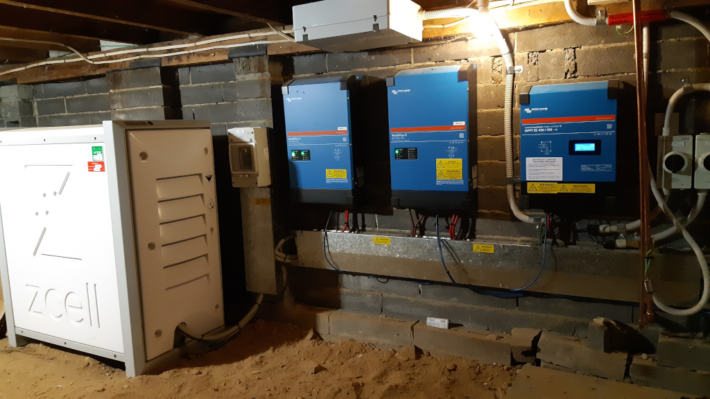
    Redflow batteries are excellent because you can 100% cycle them every day, and they aren’t a giant lump of lithium strapped to your house that’s impossible to put out if it bursts into flames. The catch is that they need to undergo periodic maintenance where they are completely discharged for a few hours at least every three days. If you have more than one, that’s fine because the maintenance cycles interleave (it’s all automatic). If you only have one, you can’t survive grid outages if you’re in a maintenance period


    From https://ourobengr.com/2022/07/keeping-the-battery-full/

    There are three goals somewhat in tension with each other here:

    • Keep the battery full, except during maintenance cycles.
    • Don’t let the battery get too full immediately before a maintenance cycle, lest the discharge take too long and maintenance still be active the following morning.
    • Don’t schedule charges during peak electricity times (we still want to draw the battery down then, to avoid using the expensive gold plated electrons the power company sends down the wire between 07:00-10:00 and 16:00-21:00).

    Here’s the solution I came up with:

    • On non-maintenance cycle days, set two no-limit scheduled charges, one from 10:00 for 6 hours, the other from 21:00 for 10 hours. That means the battery will be charged from the grid and/or the sun continuously, except for peak electricity times, when it will be drawn down. Our loads aren’t high enough to completely deplete the battery during peak times, so there will always be some juice in case of a grid outage on non-maintenance cycle days.
    • On maintenance cycle days, set a 50% limit scheduled charge from 13:00 for 3 hours, so the battery won’t be too full before that evening’s maintenance cycle, which kicks in at sunset. The day after a maintenance cycle, set a no limit scheduled charge from 03:00 for 4 hours. At our site, maintenance has almost always finished before 03:00, so there’s no conflict here, and we still have time to get some charge into the battery to handle the next morning’s peak.

    He then shows us his Python code for implementing this with his power electronics hardware. And it sounds like it works!


    Flow batteries and inverters installed in the field 
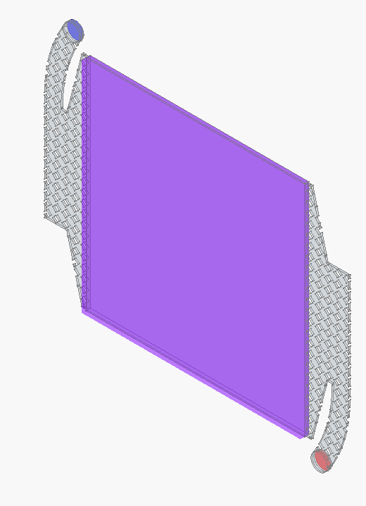
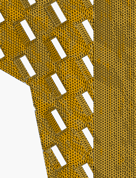
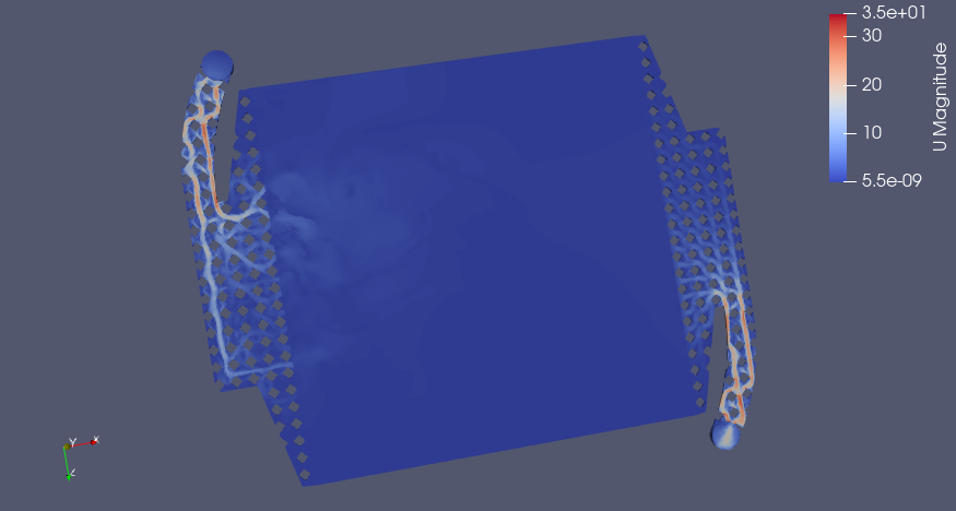
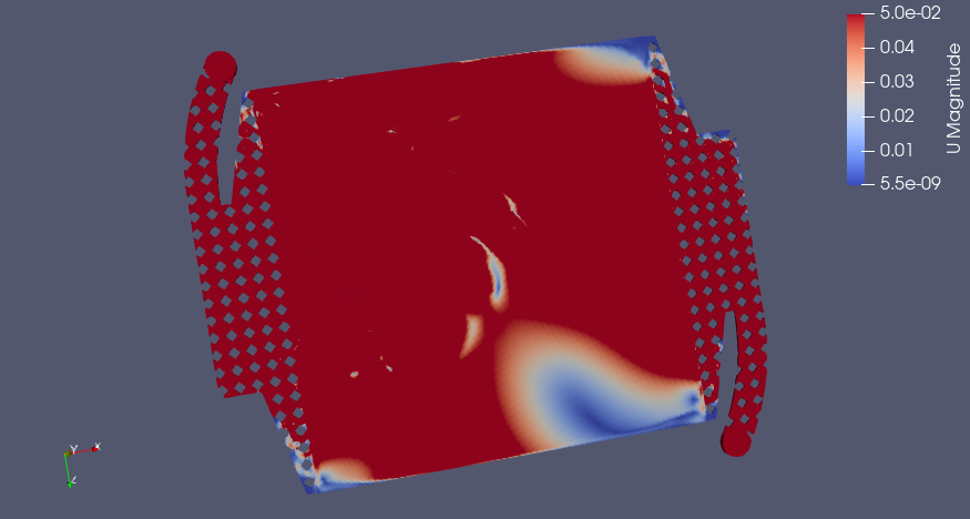
CC BY-SA Tim Serong, from https://ourobengr.com/2022/04/go-with-the-flow/

    Simon, who knows and understands how the ZCell behaves during maintenance, explained about the Energy Extraction Device, which is part of the unit whose purpose is to deliberately drain the battery down to zero for maintenance in a timely fashion.

    It looked like it was the EED being over-drawn, regardless of how much energy was still in the battery. It turns out there’s a thing that the ZCell does to handle surge demand when the EED is on, called an “EED switchback”. ZCells internally have three contactors, for Charge, Discharge and EED (also known as Strip). In normal operation, the C and D contactors are on, and E is off, so the battery can be charged or discharged at will, and the EED is doing nothing. During maintenance, the EED comes on, but it can’t deliver more than 20 amps. If the site pulls more than the EED can supply, the battery goes back to normal operation (C and D on, E off) while the high demand is present. Once the high demand goes away, it switches the EED back on, to keep discharging at the normal rate of 1kW. But, by default, that switchback process only happens five times per battery maintenance cycle so as to avoid the potential for excessive cycling of the contactors in weird edge cases.

    The delay did however allow me to spend some time messing around with scheduled charges to see if there was a cost benefit to grid-charging the battery during off-peak times, then drawing it back down during peak, because the reality is we’re going to want to do this in winter when there’s not much sun, so why not try it out in advance? TL;DR: Yes, it’s worth grid charging the battery off-peak, provided you use all that power during peak times, but it’s a bit irritating trying to figure out exactly what you’ll save. In one of my tests it was the difference between paying $3.85 for about 20kWh of usable electricity in a 24 hour period versus paying $4.70, so it’s not insignificant.

    That’s about the end of the story. The system is brilliant, and we could not be happier with the support we’ve received from Simon at Redflow, who’s been extremely generous with his time and knowledge, and Murray and Rhys of Lifestyle Electrical Services. Thanks for everything guys, I’ve learned a lot. In the eight months the system has been running we’ve generated 4631kWh of electricity and “only” sent 588kWh to the grid, which means we’ve used 87% of what we generated locally – much better than the pre-battery figure of 45%. I suspect we’ve reduced the amount of power we pull from the grid by about 30% too, but I’ll have to wait until we have a full year’s worth of data to be sure. We’ve also survived or shortened at least five grid outages with durations from a few minutes to a few hours.

    The next thing to do is get a second ZCell, and possibly eventually think about a third. Given our current generation capability, two ZCells would allow us to store and utilise 100% of our generated power locally. We’d also have the ability to handle grid outages at any time, because with two batteries the maintenance cycles interleave and they can be configured to always ensure there’s a minimum amount of charge somewhere.


    From the linked post above:

    Murray needed to come out anyway to replace the carbon sock in the ZCell (a small item of annual maintenance) ...
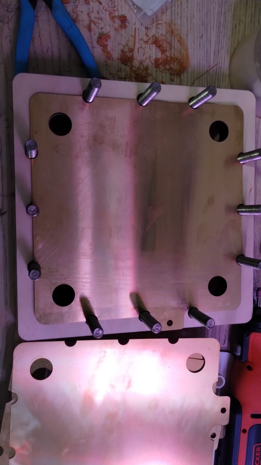
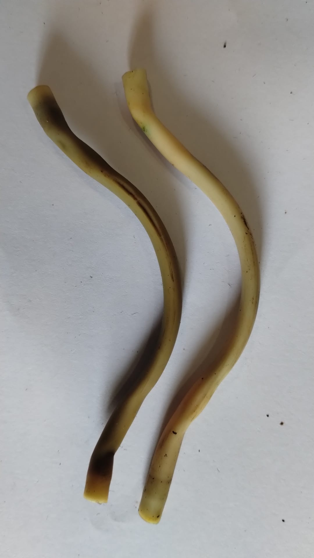
    This leads to the next little bit of fun. The carbon sock is a thing that sits inside the zinc electrolyte tank and helps to keep the electrolyte pH in the correct operating range. Unfortunately I didn’t manage to get a photo of one, but they look a bit like door snakes. Replacing the carbon sock means opening the case, popping one side of the Gas Handling Unit (GHU) off the tank, pulling out the old sock and putting in a new one. Here’s a picture of the ZCell with the back of the case off, indicating where the carbon sock goes:
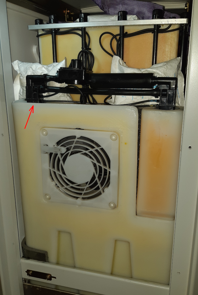
    e250812e-d2ec-475a-a2e2-79286e9ddf2b-image.png
    CC BY-SA Tim Serong
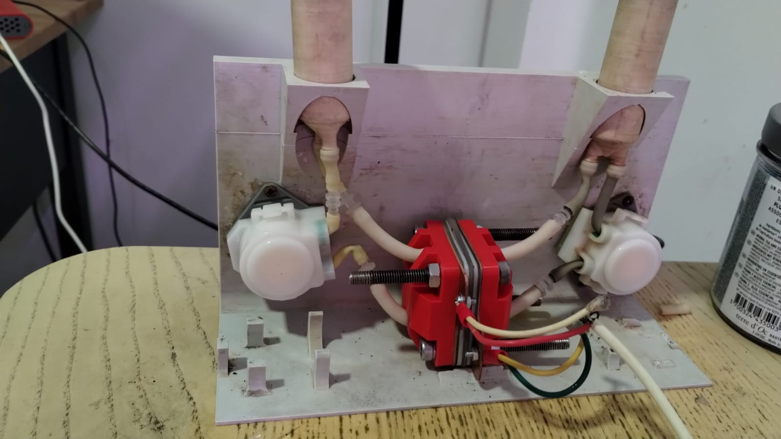
    "The tank on the left (with the cooling fan) is for zinc electrolyte. The tank on the right is for bromine electrolyte. The blocky assembly of pipes going into both tanks is the GHU. The rectangular box behind that contains the electrode stacks."

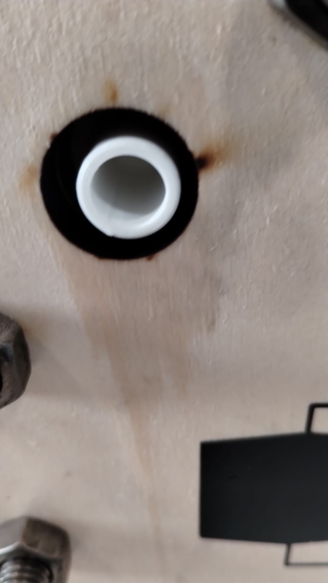
    When Murray popped the GHU off, he noticed that one of the larger pipes on one side had perished slightly. Thankfully he happened to have a spare GHU with him so was able to replace the assembly immediately. All was well until later that afternoon, when the battery indicated hardware failure due to “Leak 1 Trip” and shut itself down out of an abundance of caution. Upon further investigation the next day, Murry and I discovered there was a tiny split in one of the little hoses going into the GHU which was letting the electrolyte drip out.
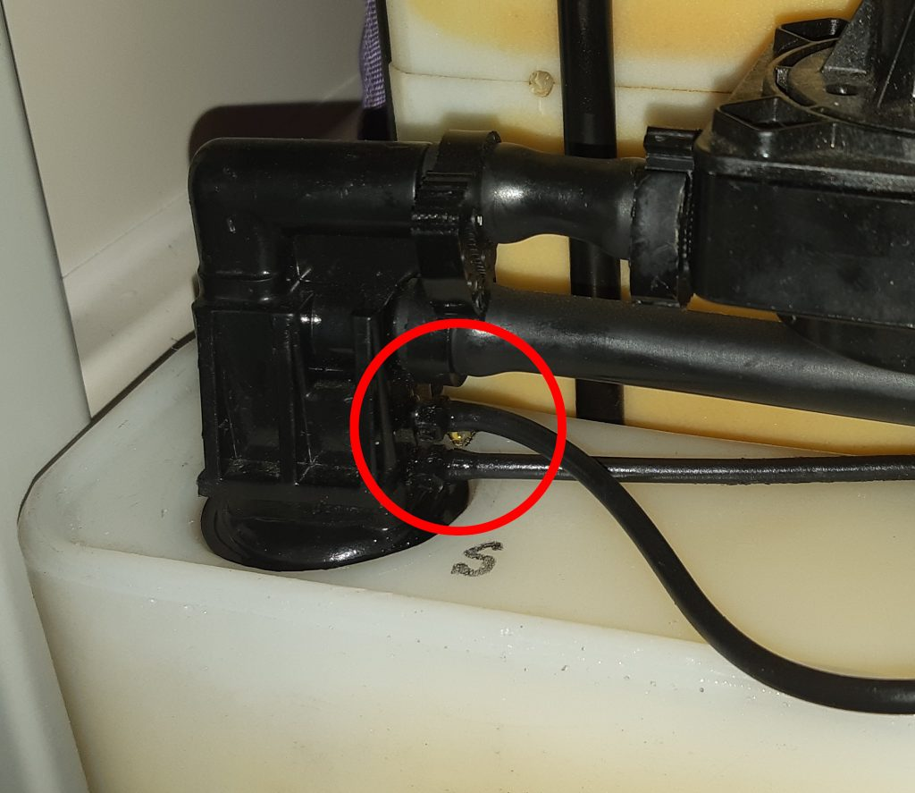
    a9069db9-200b-4f51-b8af-629477b80597-image.png
    CC BY-SA Tim Serong

    😧 😧

    bff80035-32fd-411f-803e-2fde41fa2df9-image.png
    CC BY-SA Tim Serong

    This small electrolyte leak was caught lower down in the battery, where the leak sensor is. Murray sucked the leaked electrolyte out of there, re-terminated that little hose and we were back in business. I was happy to learn that Redflow had obviously thought about the possibility of this type of failure and handled it. As I said to Murray at the time, we’d rather have a battery that leaks then turns itself off than a battery that catches fire! ... Aside from those two interesting events, the rest of the year of operation was largely quite boring, which is exactly what one wants from a power system.

    Bearing all that in mind, my general advice to anyone else with a single ZCell system (aside from maybe adding scheduled charges to time-shift expensive peak electricity) is to just leave it alone and let it do its thing. You’ll use most of your locally generated electricity onsite, you’ll save some money on your power bills, and you’ll avoid some, but not all, grid outages. This is a pretty good position to be in.

    General Discussion redflow solar victron

  • Choice of plastic
    kirkK kirk

    Great questions - our starting point was this paper, there are a lot of citations there to other papers where FDM materials have been tested in different chemical solutions. They have a discussion on why they chose ABS and PP as materials for testing flow battery chemistries with, they mention PETG as an option, but don't test it (and I don't think it would work for us right now). Fig. 2 is very relevant:

    image.png

    For the chemistries we look at now - transition metal halides - the results for DI water, sulfuric acid, hydrochloric acid, and sodium chloride salt solution are probably the most relevant, given the pH and ions present in solution.

    In their paper, they struggle to print sufficiently watertight PP prints, but they are able to get good enough ABS prints. They test the most common vanadium-based electrolyte in their setup, which is acidic, and chemically compatible with ABS. However, we specifically don't want to start with vanadium since it is relatively expensive, hard to get, and toxic - with respect to our chosen starting chemistry of zinc-iodide.

    The tradeoff here is - when charged, the zinc-iodide chemistry's positive electrolyte contains iodine, usually in the form of the triiodide complex.

    4dd962e7-c569-4bc4-aa25-a56357522231-image.png

    Iodine and triiodide have very peculiar chemical compatibility requirements, and they are NOT compatible with ABS or PETG, so we have to use PP. If we are able to develop an alternative chemistry that is available, cheap, and safe to work with, then ABS or PETG may be an option in the future.

    We have designed our cell in such a way that we seem to be able to get "tight" enough prints to have leakage not be an issue in our benchtop tests. However, we are only printing cells with a 2 cm2 active area, whereas the paper above is testing 25 cm2. Time will tell if our process can scale up - I'm right now in the process of designing a flow frame for a 175 cm2 flow frame for our first larger-format cell, and the idea is to FDM print this at first.

    In "real" industry applications, the flow frames of a flow battery are, to my knowledge, injection or compression molded. PP and HDPE are common polymers for this, and I have heard of PVC also, for particular chemistries.

    General Discussion

  • MyStat PCBs for free
    kirkK kirk

    @sepi @czahl @danielfp248 I have enabled the chat plugin just now! With min. user reputation of 2 to try to prevent spam.

    Public and private chat groups/PMs now possible, though I don't think it's encrypted if that's a concern (we are hosted by NodeBB).

    General Discussion

  • Designing the large-format cell
    kirkK kirk

    The current collectors and endplates as-received from SendCutSend in the US, laser-cut and milled, respectively:
    IMG_20250621_074644.jpg

    Some more pics:
    Open source battery project - 2025-08-04 08.47.13.jpg

    Open source battery project - 2025-08-04 08.47.59.jpg

    Open source battery project - 2025-08-04 08.47.56.jpg

    Open source battery project - 2025-08-04 08.47.47.jpg

    General Discussion

  • Long term cycling of our Flow Battery kit using a Zn-I chemistry
    kirkK kirk

    Nice work, Daniel. I am thinking of plumbing solutions to the imbalance issue:

    From A review of all-vanadium redox flow battery durability:

    After studying the capacity fade for mixed acid electrolyte, UET [154] found that, during long‐term operation, the ratio of catholyte and anolyte concentration remained constant: 1.3:1. Based on this finding, they designed an overflow system with different volume (volume ratio: 1.3:1) anolyte and catholyte tanks, in which the volume ratio and total vanadium were kept constant. With the new design, the VRFB achieved long term capacity and efficiency stability. However, this design is only valid for the mixed acid electrolyte system. Recently, Wang et al [152] developed an electrolyte reflow method to solve the electrolyte imbalance issue for the sulfuric acidvanadium electrolyte system. Figure 10 shows the schematic of their method; without reflow, eventually all of the anolyte will move to the catholyte tank, while with reflow, the anolyte tank will always contain some electrolyte. Similar to the UET method, the volume ratio of catholyte to anolyte is a key parameter affecting the capacity stability and is highly dependent on the operating current density. Cycle life and total capacity were all improved with the reflow method.

    There is also Capacity balancing for vanadium redox flow batteries through electrolyte overflow but it was retracted - they think they accidentally had a pinhole in their membrane for the test. But they did build a real overflow system:
    aceadcdb-fb4d-4387-b6c6-9b95a79cc192-image.png

    Blogs fbrc flowbattery zniflowbattery

  • Come see us at FOSDEM! (or online!)
    kirkK kirk

    The Flow Battery Research Collective is excited to present at FOSDEM this weekend! Come see us in-person or online.

    Details are all here.

    Track: Energy: Accelerating the Transition through Open Source
    Room: H.2214
    Day: Sunday
    Start: 10:55 (Brussels)
    End: 11:15
    Video only: h2214
    Chat: Join the conversation!

    Daniel and Josh will be presenting on our work. Looking forward to connecting with the many cool projects in our devroom and others, as well as hopefully meeting with other @nlnet@nlnet.nl and @ngizero@mastodon.xyz projects!

    Exploded view of a flow battery test cell

    Assembled test cell in a jig

    @fosdem@fosstodon.org

    Announcements batteries openscience fosdem opensource energystorage

  • Zinc-Iodide
    kirkK kirk

    This is why we can't use BPT tubing in the peristaltic pumps of the dev kit for this chemistry:

    image.png

    @danielfp@chemisting.com

    anolyte (right) and catholyte (left) tubings. They are both exact same external and internal diameters. The catholyte one is obviously slashed and the catholyte pump had a lot of iodine inside. So, lastest longer but definitely not impervious to it

    Electrolyte Development

  • How should we control the centrifugal pumps? TRIAC/thyristor etc? Need help from controls/electrical people
    kirkK kirk

    We do need centrifugal pumps that are magnetically driven, with no rotating seals - that's a must.

    This is only a test rig, but relevant: https://www.hardware-x.com/article/S2468-0672(20)30049-3/fulltext (and they used a stepper motor to drive the pump)

    General Discussion

  • Come see us at FOSDEM! (or online!)
    kirkK kirk

    Our talk is now viewable on PeerTube here: https://spectra.video/w/6BddEiwBqRMHSbC9qBLBz9

    Announcements batteries openscience fosdem opensource energystorage

  • Alternative Electrolytes
    kirkK kirk

    thanks for this info! FYI I forked your post into a separate topic into the "Electrolyte Development" category just to keep the intro thread relevant.

    I am a big fan of Savinell's and Wainright's work at Case! Savinell was on on the all-iron RFB development quite a long time ago... this is one of my highlights from one of his papers in 1981 (!):

    image.png
    Source:
    Hruska, L.W. and Savinell, R.F. (1981). Investigation of Factors Affecting Performance of the Iron‐Redox Battery. Journal of The Electrochemical Society. https://doi.org/10.1149/1.2127366.

    Showing quite clearly the issue of iron kinetics, even at 60 C...


    @muntasirms said in Alternative Electrolytes:

    In flow batteries, any time you have plating you end up re-tying power density and energy density through that half cell.

    Yes, unfortunately, would love to have an all-liquid configuration that plays well with porous separators but asides from iron-chromium (which also has its own set of cons, like HER/high purity req's) there isn't much out there that's easy to start with, which is why we're starting with zinc to get things going.

    @muntasirms said in Alternative Electrolytes:

    They attempted to scale but really struggled with having a performant enough slurry electrode that wasn't too viscous.

    I saw this, I think I skimmed their ARPA-E report (https://www.osti.gov/biblio/1506426) and they also had issues with the cell plugging. IIRC they also licensed the tech to an Australian company?

    @muntasirms said in Alternative Electrolytes:

    Have you guys looked into water-in-salt electrolytes? They involve dissolving a ton of a supporting electrolyte to the point where they lower the activity of water and suppress HER. I've seen some work using acetate salts and this one using magnesium chloride to support even iron plating - and I've replicated it successfully. The study plates on copper like I mentioned earlier, but I also got it to plate on grafoil.

    I am a big fan of this type of electrolyte engineering! The viscosity can also become an issue with this sort of approach too, no? (You are from now the FBRC viscosity expert 😅) I see in that paper though they only cycle up to 0.5 M [Fe], which is quite low in terms of energy density (~8 Wh/L if I'm not mistaken). But it seems solid enough to at least test in the development kit as an exercise. Also a huge confidence boost that you were able to reproduce it and make it plate on grafoil!

    @muntasirms said in Alternative Electrolytes:

    I did a little study collecting the centralization/governance of various metals and ranked aqueous battery chemistries by cost and "criticality".

    Definitely of interest, would love to see it if you're able to share - it's one of my concerns with iodine chemistries at scale (avoiding artisanal iodine production from seaweed).

    Electrolyte Development

  • Hi :D
    kirkK kirk

    Hey @BillySmith welcome!

    That's great that you and a few fellow hackers are interested in building a dev kit - let us know how we can help! I am still scheming up the large-format cell. I would really like it if we could FDM print it in polypropylene, but not sure if that's feasible yet. I have some initial thoughts and pictures related to the large-format cell here: https://fbrc.nodebb.com/topic/11/designing-the-flow-frames-for-the-large-format-cell

    In the dev kit, we were using peristaltic pumps which failed due to incorrect tubing - those pump at about 60 mL/min. In the larger cell, we will have to use centrifugal ones like the ones you linked to, but we can't have a rotating seal like in that link shows - we need pumps driven with a magentic coupling (also called mag drive, hermetic seal, etc). Here is another forum thread on it with an exploded view: https://fbrc.nodebb.com/topic/8/how-should-we-control-the-centrifugal-pumps-triac-thyristor-etc-need-help-from-controls-electrical-people/12?_=1739427920720 . That pump is the smallest mag drive I could find, suitable for "chemicals" (so made from polypropylene or PVDF) - and it's around 6 L/min flow, so two orders of magnitude higher!

    They are made from polypropylene, which is ideal for our case. Right now we are trying to figure out how to control/modulate their speed/flow, since they came with cheap AC motors.


    Again, warm welcome to the project and please let us know how you get on with the dev kit! We are still finalizing a suitable first chemistry for stable cycling for the kit.

    General Discussion

  • Micro-update
    kirkK kirk

    The pump's magnetic coupling:

    https://spectra.video/w/ibcPCanyfyvogdxCcV8Qsp

    General Discussion

  • How should we control the centrifugal pumps? TRIAC/thyristor etc? Need help from controls/electrical people
    kirkK kirk

    Tested the pumps today, they work just fine switched on 110 V AC, will try the triac, if that doesn't work/it fries the motor, will disassemble and try to get a different motor on there.

    Video of pumps running: https://spectra.video/w/9VddoPTvMvDCJ121B4fabf

    General Discussion

  • How should we control the centrifugal pumps? TRIAC/thyristor etc? Need help from controls/electrical people
    kirkK kirk

    @methylzero@mast.hpc.social said in How should we control the centrifugal pumps? TRIAC/thyristor etc? Need help from controls/electrical people:

    Nice! Better than I expected honestly. At the low end of the speed range it sounds a bit unhappy. The thermal protection is only TP111 so it may not be fast enough to save the motor if it is stalled.
    If this motor does work out, the manufacturer can make bigger ones and apparently you can choose the wet-side material. http://www.china-haiyi.com/product-48054-173640.html

    Thank! I read some stuff that TRIACs can work for very small motors, and indeed this is only around 6 W, so I figured why not just try it. Yes, at the low end it made some funny sounds, nothing horrible, but this is not definitely not the optimal control strategy. It should hopefully allow us to do single-cell flow testing at close-to-appropriate flowrates, without having crazy fast flow or having to add a bunch of (chemically resistant) plumbing like a bypass/pump-around. For wet-side I think they have two standard options of PP and PVDF for the housing/impeller. Also, for some bigger pumps, they offer BLDC motors stock, apparently, which should be easier to slow down efficiently. Didn't know that TP111 designation either - sounds like it should auto-shut off if it gets too hot at steady state, but won't protect from a stall.

    Also, just FYI, R.Flo, a Ukrainian all-iron RFB startup, posted a pic on LinkedIn with these pumps:
    80236eb7-7077-469a-85ba-e4536d3b2418-image.png

    Which look to be the same version, but larger.

    @methylzero@mast.hpc.social said in How should we control the centrifugal pumps? TRIAC/thyristor etc? Need help from controls/electrical people:

    But one thing not good about these pumps is that they might not work great with really dense solutions, max. density is 1.1-1.3 depending on the model, which is .... not much.

    Yeah I saw this and... we will cross that bridge if/when we get to it 😅 at this low of a price point I read the datasheets with a shaker of salt.

    From CRC handbook for potassium iodide (just as a reference point for a salt we currently test with):
    267c9247-475e-4c6c-aae6-fca45c131de9-image.png

    In real electrolytes we'll have other salts present at the same time, but even with a 1.3 SG max we may get to reasonable concentrations---as in, high enough to allow us to build out the rest of the system for a prototype. I figure over 1.3 SG the pump either fails faster or has otherwise reduced performance, but maybe we'll find out the hard way 😅

    General Discussion
  • Login

  • Don't have an account? Register

  • Login or register to search.
Powered by NodeBB Contributors
  • First post
    Last post
0
  • Categories
  • Recent
  • Tags
  • Popular
  • Users
  • Groups