Think of this as your global discovery feed. It brings together interesting discussions from across the web and other communities, all in one place.
While you can browse what's trending now, the best way to use this feed is to make it your own. By creating an account, you can follow specific creators and topics to filter out the noise and see only what matters to you.
Ready to dive in? Create an account to start following others, get notified when people reply to you, and save your favorite finds.
Filmed myself building a cell so you can see the whole process start-to-finish! Still working on updating the documentation for the clampable-cell branch. It works pretty darn well without any bolts.
Over a couple weekends, I've been working on parameterizing the FBRC model. It was borne of a couple kinks I ran into - I would want to adjust bolt or hose barb diameters based on what I had lying around, or scale the model down for smaller lab scale setups while maintaining control over electrode thickness for lab experiments. The idea is to adjust a single parameter in a script, which then adjusts the appropriate dimension in all the design files, then spits them out for fabrication.
The result is a single "model" with flexibility to adapt plumbing, sizing, and construction according to your particular application. So for example, the same parameterized model can spit out
a small cell with hose barbs for lab scale applications (18cm2 electrode area)
a medium size cell (using the current FBRC large format sizing)
or a "fat stack" (3500cm^2) with extra, thicker bolts
all from the same parameterized design. Once the designs are generated, all the associated STL, STEP, and DXF files can be downloaded for fabrication.
I briefly discuss it in the video, but because the models are parameterized, it's easier to programmatically keep track of the locations of ports, walls, manifolds, etc. That makes boundary condition declaration and the like much easier to automate as well - so I'm in the process of slotting this into an automated hydraulics/electrochemical simulation suite. Imagine generating your custom model and simulating a "digital twin" for estimates of performance prior to purchasing materials or finalizing design.
I'm very open to constructive criticism on any part of the project (from ideation to UX to engineering). Have fun fiddling with it and let me know what you think!
Also, this reminds me of the OpenAFPM project - they also use FreeCAD and provide a dashboard for people to input custom parameters for a small wind turbine generator, there is some FEM, and then design files are output. There is a video demo here: https://www.openafpm.net/cad-visualization
I know a few of the folks behind that project, I'm sure they'd be happy to give input on how to accomplish a similar goal but for flow batteries.
@trevorflowers thanks for the kind words, and please feel free to ask questions about things you don't understand! I'm writing these lab notebook entries in a concise way and not doing much explaining
On a previous post I discussed my first attempts at reproducing the Na-sulfamate based Zn-Br battery published by a group of Chinese researchers. My results showed that the chemistry works mostly as they showed, but I was unable to reproduce both the capacity and stability properties of their testing results. This post summarizes some additional research results I obtained with this chemistry and why, I believe, my results have been unable to match theirs.
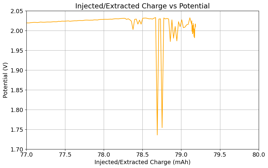
From the get go, my results showed significant declines in capacity when charging to the Nernst limit. This happened even at lower capacities and even at lower concentrations. Oftentimes with deterioration of the charging potential but sometimes with no changes in charging potential at all. This was irrespective of whether the buffer was prepared with just KAc additions, with HAc+KAc or with different buffer strengths. Additional HAc additions did not recover this capacity, which makes me believe that the losses are due to some permanent loss of the sulfamate inventory. Since these losses often happened with very little or no deterioration of the average charging potential, it also makes me believe these are not due to problems with Zn dissolution. After I opened the batteries I also saw no accumulation of metallic Zn on the anode felt or separator (while when it’s a problem with Zn reversibility you see some clear dead Zn remains).
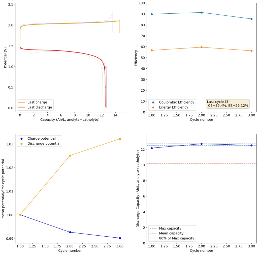
Charging to the Nernst limit (to 2.1V) shows some clear capacity losses as a function of cycling. The above is for a 0.5M ZnBr2, 0.5M KBr, 0.5M Na-Sulfamate solution in a 5 pH buffer prepared with KAc and 8% Acetic acid. 100% SOC would be close to 6.7Ah/L, as the reaction is limited by sulfamate on the catholyte side. Catholyte and anolyte electrolytes are identical on start. 25mA/cm2 current.
If you read the original Nature paper carefully, you’ll also see that none of their charge curves ever reach the Nernst limit but they are carefully capacity limited to some predetermined value. This initially makes no sense – why would you choose to not use all your capacity? – unless there was a problem with either Zn dendrites or with some other side reaction. Given that Zn dendrites don’t seem to short the battery until much higher capacities, it seems clear that the problem must be elsewhere.
To test this hypothesis I tested the reversibility at 50% of the SOC. It is clear that the deterioration slows down at this point. It is also clear that my cathode – being normal felt – is way less electrochemically active than the carbon nanotube and N-doped felt that is actually used by the Chinese research group. This makes me believe that sulfamate starts degrading at high SOC values, perhaps because N-Br sulfamate starts becoming so concentrated that double bromination becomes possible and then the double brominated N sulfamate is much more likely to decompose with degradation of the sulfamate, possibly into sulfate, ammonium and other brominated side products, like bromate or hypobromous acid. Perhaps the fancy cathode of the Chinese research group has much faster kinetics and is able to handle much faster Br transfers into sulfamate without exposing already brominated sulfamate to double brominations. However, since they don’t charge to the Nernst limit, it makes me believe that they still saw this when they tried charging to higher potentials, hence they didn’t.
Perhaps the most important fact is that capacity recovers if you add more sulfamate, which pretty much confirms that the problem is due to sulfamate degradation.
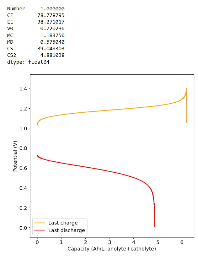
Same battery as described on the previous image but only charged to 3Ah/L capacity at same current density.
The above implies that sulfamate, while able to support Zn-Br chemistry, is not as stable as it seems on the paper. Careful control over the charged capacity is needed and cathodes that allow very good kinetics for the bromination of the sulfamate are also required. Without significant engineering of the cathode material, it seems that you are limited to around 50% of the SOC – based on the sulfamate – if you want to avoid degradation of the sulfamate as a function of time.
Also, capacities reported by the Chinese group seem to be based only on their catholyte volumes, therefore you have to divide all their values in half if you want to make real comparisons to Ah/L values. They still reach very high capacity values, very close to the actual 100% SOC levels for these systems, although without ever taking the batteries to the Nernst limit. My battery has much higher internal resistance than theirs, which also explains a lot of this difference (as my kinetics are slower, my potential increases much earlier).
Long story short, you cannot just add sulfamate to a Zn-Br electrolyte and expect the battery to work like magic. As it is always the case in batteries, the devil is in the details.
This video seems to be AI generated and doesn't have that much real information? I have seen Ca-ion systems from (I think) a German group that looked good, but had a lot of organic synthetic steps if I remember correctly.
The cost per kWh of this is too high, the use of organic materials and ion exchange membranes puts this closer to what people do in academia and further from the cells that can be reasonably fabricated using DIY approaches. The use of an ion exchange membrane likely reduces the lifetime of this cell a lot. For a static cell, I think the sulfuric acid Cu/Mn battery we have discussed before is far more promising. That chemistry requires no exchange membranes, uses only commodity inorganic materials and cycles to 30-40Wh/L.
For pure Fe batteries I am much more inclined to the Fe flow batteries.
There's a lot I would love to add to this community. I think the way traditional methodology for this technology needs to be reapproached. Firstly, by using my open sourced membrane recipe you can glue it directly into a PVC cell. Secondly, using foam core PVC sheets which are readily available and cheap from cabinet shops like imeca allows for complex flow cell designs to be easily and rapidly produced with a simple CNC router on various sizes. I have a flow cell design already I'll be glad to upload. I'm new here so sorry there's a lot I love to want to share and am doing things one thing at a time.
This would be great to see! Feel free to start a thread in @general-discussion about your cell design. We had tossed around the idea of 2D-material milling/laser approaches to flow frames, but have stuck with 3D printed designs for now so that we can have internal geometries in the flow frames - 2D would certainly be easier and cheaper to make, but I was hesitant about the increased gasketing required/adhesives for sealing.
The key aspect of using the proposed PVC membrane recipe together with the pvc foam board actually completely eliminates the need for gaskets. You simply glue the membrane in place since its also made from pvc. Overall there's far less labor and requirements, forming a sealed (technically welded) bonded cell for a fraction of the price that 3d printing would cost. The long term goal and my personal next goal is to get into injection molding which of course is the best option.
Ill see about uploading the cell fusion 360 model soon depending on if people even care or not. But the point is the core principle idea of being able to use much cheaper pvc foam board material and mass produce these cells at a much better scale than one layer at a time with 3d printing. I was able to make unique geometries needed for flow cells with my 2d design.
As a comparison, you can buy these foam boards for $60-80 for 1/2" or 3/4" from imeca for a full 4x8ft sheet
@rowow said in Using cnc router cut PVC foam boards as cell frame:
The long term goal and my personal next goal is to get into injection molding which of course is the best option.
At scale, definitely!
@rowow said in Using cnc router cut PVC foam boards as cell frame:
Ill see about uploading the cell fusion 360 model
A .step file would also be great so I could look at it in FreeCAD! I don't have a Fusion 360 license. I'd be curious to see if we could take a similar approach.
Hi all, been planning some improvements to the dev kit that are underway, based on some ideas exchanged at a conference with some other open-source flow battery projects (Redoxino and the team at QUB).
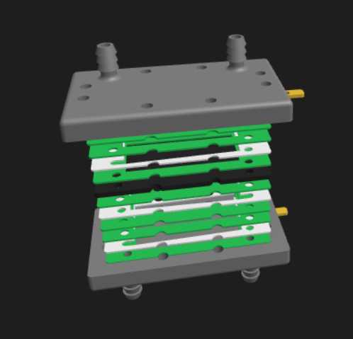
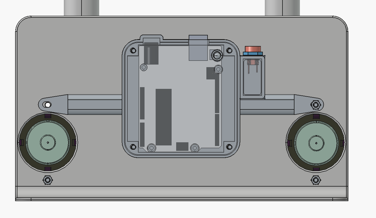
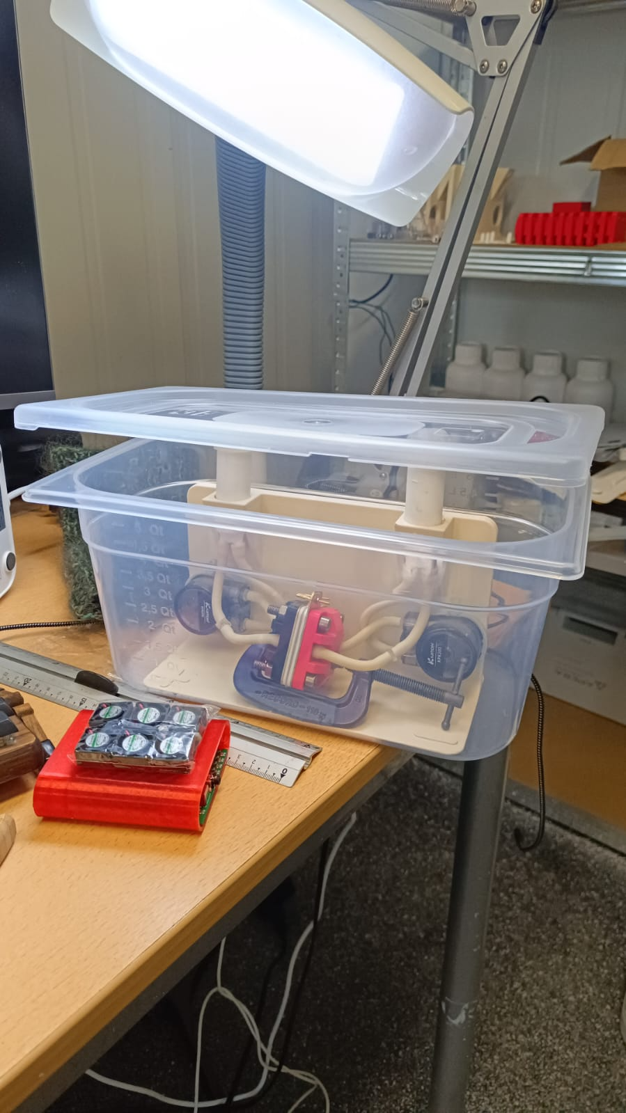
It's mostly to improve ergonomics - there is now a case to hold the arduino and wires on the rear of the cell:
We also realized you can just clamp the cell shut with a 2-inch C-clamp instead of using the bolts, and it seals well:
Note, the new endplates here used are backwards-compatible with previous gaskets/graphite plates/brass current collectors, so no need to recut anything. Moving forward though, the design files for those components will change to reflect the need for only two alignment pin holes instead of the four bolt holes.
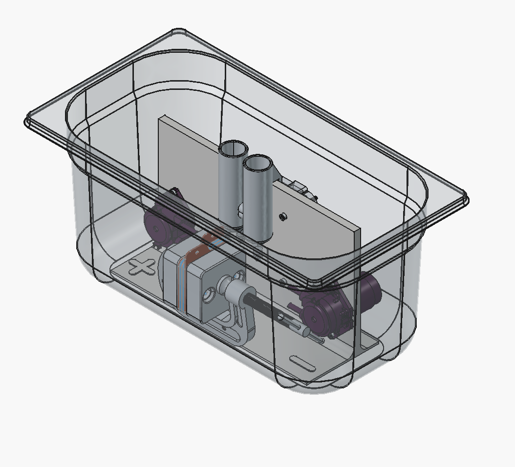
And based on Redoxino's presentation at the Nordic Flow Battery Network meeting, Gastronorm (GN) containers are a nice standard to use for secondary containment, it seems with some tweaks we could fit the entire kit into a GN 1/3 150 mm deep container, which are a standard for industrial kitchens worldwide (and available in polymers like PP and PC).
Need to make the reservoirs shorter or mounted lower somehow, and maybe make a holder in the jig for the C-clamp, so that it's in a fixed position.
@doho said in Upcoming improvements to the dev kit:
I have try-ed to download Your new files from github (.stl and .pdf), but the files all appeared as broken, even in github.
The files to sprint for the new endplates are here: https://codeberg.org/FBRC/RFB-dev-kit/src/branch/clampable-cell/CAD/exports
[image: 1771858819246-1c46bc80-7e99-4780-8178-46d24a289a32-image.png]
I haven't updated the new
You have to download them individually, unless you clone the repository with Git LFS set up---the large CAD files are handled with LFS and without LFS installed downloading the repository just downlaods a pointer/reference to the CAD file, not the actual file (at least that's how I understand it).
Let me know if this works for you!
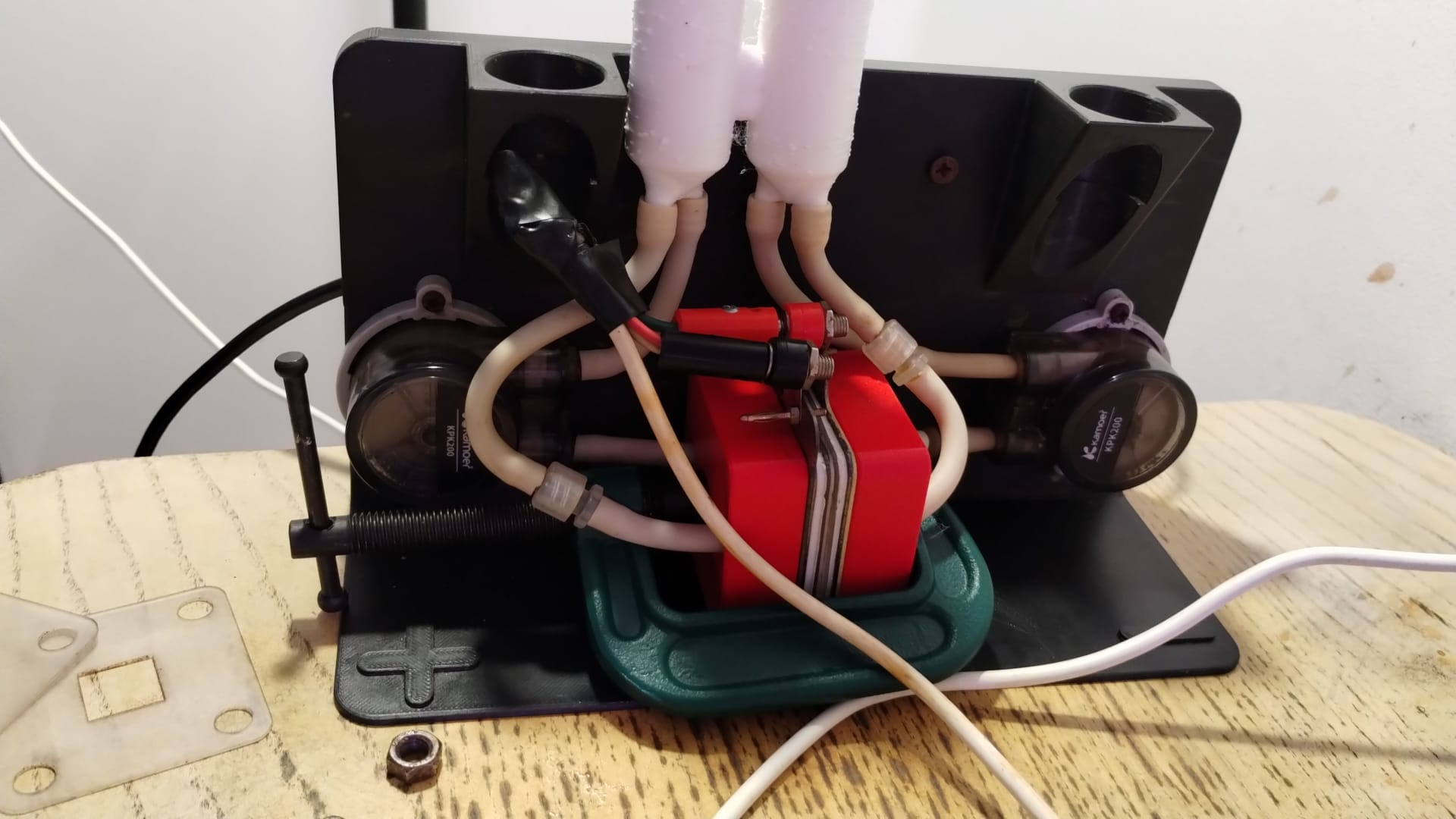
As I had to change the tubes in my pumps (they were the wrong tube type),(thanks @sepi) I also changed the connectors to Luer Lock .
Therefore it was necessary to enlarge the boreholes in the endplates and in the brass-plates to 10.5 mm to get the female Luer Lock part through.
And I changed my construction to sucking from the cells.
Some other thoughts: @danielfp248 In your picture of 08.01.26 you put the pump for suction on the lower side of the cell, why?
In my opinion it would be better to connect the pump upper side to avoid air in the system as I did in my setup.
@kirk
your new approach for the test cell seems veri interesting. But for getting reproducible resultants the flow through the cell should be down to up, but not horizontal (how much would be air isolating in the chamber when changing parts?)
I do not have an idea for a reasonable physical layout for a really simple change of the test-chamber, but I will think over.
Printing materials I have used:
Parts not in contact with chemicals: PETG, works very well
PP: My 1st: (Yousu),all surfaces o.k, but all barbed broke. 2nd: Innovatefil PP GF worked very well, but the upper surface was rough, tests will come.
Very nice work @doho ! It's great to see your setup.
@doho said in My Suction Luer Lock:
But for getting reproducible resultants the flow through the cell should be down to up, but not horizontal (how much would be air isolating in the chamber when changing parts?)
This is a good point, from what I've seen in other applications cells should generally clear air/produced gases by flowing against gravity from bottom to top, that is still possible with the new setup but the tubing from the pump outlet to cell inlet would have to be slightly longer. In my jig redesign I'll take this into account when writing the documentation.
I just wrote a blog post sharing my first results testing the Zn-Br chemistry recently published by a Chinese group. Sodium sulfamate is not very easy to get, but I was able to source it from labdiscounter.nl in the EU. If any of you are in labs where you can also test this chemistry, I would be happy to hear about your thoughts and/or results.
A recent Chinese Nature paper showed how Sodium sulfamate can be used in Zn-Br batteries to sequester active Br2 into an N-bromosulfamate that is much less aggressive, much more water soluble and even more easily electrochemically reversible than elemental bromine. I also wrote a recent post discussing the potential use of nicotinamide to achieve this (plot twist, it doesn’t work as the nicotinamide Zn complex is not very soluble). In today’s post I want to share with you my attempts at reproducing this chemistry of the Chinese paper using our open source flow battery dev kit.
The paper is very extensive and shares multiple formulations, they share a formulation for normal asymmetric cells as well as formulations to run the batteries using microporous Daramic membranes. Thankfully I have a bunch of 900um Daramic (thanks a lot to Daramic who donated these membranes to us for research). I bought some Sodium sulfamate (NaSA), Zinc bromide (ZnBr2), Potassium bromide (KBr) and potassium acetate (KAc) and proceeded to run some tests.
Tests using 1M ZnBr2, 1M KBr, 2M KAc, 1M NaSA. Charge and discharge were both done at 30mA/cm2.
My tests using the formulations that they disclose exclusively for daramic were not very successful. Formulations using only ZnBr2, KAc and NaSA suffer from either lower capacities because of lower conductivity or issues with hydrogen evolution. This was specially the case when I tried the ZnBr2 1M, KAc 1.5M, NaSA1.5M formulation, which they suggest in the supporting information to reach >50Ah/L. However I think this is a typo and they meant 2M ZnBr2. If you read that paragraph in the supporting information closely you’ll realize why this is the case (they previously refer to a ZnBr2 1M solution and then say this is basically 2x that, but still write it as ZnBr2 1M).
I then proceeded to test using some of the electrolytes they suggest for asymmetric cells, which were much more successful. In particular the 1M ZnBr2, 2M KAc, 1M KBr and 1M NaSA was great, with high CE values and decent EE values (see graph above). I didn’t experience dendrites before reaching the Nernst limit of the cells when using the 900um thick Daramic, which suggests plating is not as aggressively dendritic as with other electrolytes. However dendrites are quite evident when using 300um Daramic, suggesting you need around 300um of Daramic for every 30mAh/cm2. This might explain why the paper restricts most plating to below 90mAh/cm2 when using the 900um Daramic. I have yet to reproduce the Chinese group capacity or cycling stability values, but I believe I have validated the electrochemical principles well.
Clear evidence of dendrites at 78-79mAh (using 8mL of total electrolyte) using a 2M ZnBr2, 1.5M KAc, 1.5M NaSA electrolyte.
It is also worth noting that the Chinese group does some fancy functionalization of their felt with both nitrogen containing groups and carbon nanotubes, which aggressively boosts the conductivity and energy efficiency of the felt for the Br reactions. This is an important different that might justify why they get energy efficiencies closer to 75-80% while mine are just shy of 60%. I also haven’t optimized the compression ratio of my felt, which means that my felt might be under or over-compressed to extract the max EE in this setup. I also lack an oven to properly do air activation of the felt, so my felt is quite suboptimal and just used as-is.
Furthermore, the paper successfully tested a true flow battery setup using Ti-Br. I cannot easily buy TiOSO4 but I decided to try to innovate and test this chemistry in a fully symmetric setup coupled with 0.5M of Fe-DTPA. While Fe-DTPA isn’t expected to be fully resistant to N-bromosulfamate, I figured it might last enough to provide me with some data. Given that the redox potential of the Fe-DTPA redox couple is quite lower than Fe2+/Fe3+, I figured it should give some appreciable voltage in an Fe-DTPA/N-Br-sulfamate battery. Fe-DTPA is also quite soluble and stable at the near neutral pH that favors the N-Br-sulfamate chemistry, so it should work nicely.
Fe-DTPA 0.5M, NaSA 1M, KBr 1M, KAc 1M. Cycled at a current of 30mA/cm2.
The results above, which have never been published before, show that this chemistry works to some extent. The low CE does suggest that a significant portion of the Fe-DTPA is somehow lost, perhaps to oxidation by atmospheric oxygen (I cannot purge my cells with N2 or Argon at the moment), but also likely from just interactions with N-Bromosulfamate across the microporous membrane. With that said, it does show that the new stabilized bromosulfamate chemistry opens up the window to some very interesting options that just didn’t exist before. Perhaps I can test nicotinamide in this setup, where there is no Zn to cause it to precipitate out of solution.
Finally, I wanted to dedicate the above post to Robert Murray-Smith, a fellow chemist in the UK who passed away recently and was a key inspiration for the start of this blog. I know his passing has been very sad for a lot of us in the DIY community, the curiosity and inspiration he instilled in a lot of us will live on. Thank you Robert!
Hello, I recently open sourced a novel ion exchange membrane recipe using a high speed grinder on water softener resin and mixing with PVC cement. They can be produced for less than $1 a square yard with properties similar to other name brand ion exchange membranes. You can find more details on the following GitHub https://github.com/Rowow1/Open-sourced-off-the-shelf-ion-exchange-membrane
The patent in the GitHub describes more details, but I also made the following video where I released the files patent as a CCL1.0 license. I have lots of other ideas I would love to assist this community in but I hope this can demonstrate the significance change in scope of redox flow batteries.
Zinc bromide flow batteries have been researched very extensively during the past 30 years. There are many advantages to this chemistry, very high potential (~1.8V), high efficiencies, symmetric electrolyte and low reagent costs. Nonetheless, the disadvantages are also huge: zinc dendrites, hydrogen evolution, bromine corrosion, etc. Despite all the development, a lot of these disadvantages remain insurmountable.
A recent nature paper has disrupted the field by using sulfamate ions as a bromine scavenger. Unlike previously used complexing agents that sequestered Bromine as reactive Br3- species, the new scavenging method sequesters Bromine as an N-bromosulfamate, which is stable in solution in the timescales necessary for energy storage. Furthermore, the N-bromosulfamate is chemically much milder than elemental Br2 or Br3-, making the use of cheaper gasketing materials possible and preventing a lot of issues associated with the high reactivity of elemental bromine species.
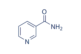
A model of the nicotinamide molecule. The Br reacts primarily with the amide group (NH2) under mildly acidic conditions.
I have been very excited by these findings and have ordered some sodium sulfamate to test this chemistry myself in our FBRC development kit. However, the development of this technology is likely not open source and it is very likely that the people involved with it want to patent it and lock down the technology. This made me think about potential alternatives that could be used outside of the sulfamate family that could also exploit the mechanism of Br storage in N-Br bonds. Such a technology might be outside the scope of their original paper and therefore be exempt from intellectual property registration.
Thinking about the stability of N-Br compounds (usually not stable at all), I immediately think about NBS and analogous chemical compounds. These are very stable reagents that are routinely used in chemical synthesis, although their aqueous solubility is very low and therefore not useful in the creation of a ZnBr2 aqueous battery.
With that said, nicotinamide (vitamin B3) is a very water soluble and readily available material that also forms a stable N-Br compound in mildly acidic conditions. This 2007 paper describes how N-bromonicotinamide can be created using elemental bromine. While N-bromine compounds from amines like this would often go through a Hoffman rearrangement to yield the corresponding amine, this doesn’t happen under mildly acidic condition in the case of nicotinamide. In fact, the 2007 paper mentions that a concentrated solution of this N-Br compound was stored for months without degradation. The solubility of nicotinamide is also very high (5-6M), compared to sodium sulfamate’s solubility limit of 1.3M at 25C.
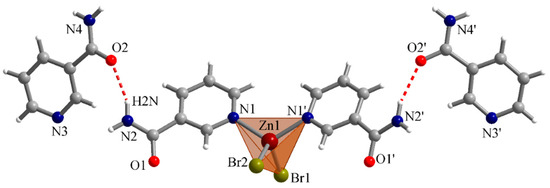
An example of a nicotinamide-Zn complex. Check this paper to learn more.
Furthermore, nicotinamide forms mono and dimeric complexes with Zn atoms through the nitrogen in their pyridine ring, which makes this nitrogen unavailable for potential deactivation with direct bromination of this N to yield the corresponding quaternary nitrogen salt (irreversible and undesirable in the context of a battery).
Given that vitamin B3 is very soluble, very low cost, already produced industrially, has a stable amide N-Br compound and is unlikely to undergo Hoffman rearrangement or similar decomposition modes, it is a great candidate to serve as a Br2 scavenger in a ZnBr2 battery. I am going to buy some vitamin B3 to test this idea out. Stay tuned for some tests of this and the sodium sulfamate chemistry.
We will be presenting at FOSDEM 2026 and hope to see you there! Kirk and Daniel will be presenting at 12:30 on Saturday, January 31 in the Energy track in room AW1.126. Full details here, including the link to the livestream (talk should also be recorded and watchable later).
The title of the talk is "Scaling up open-source batteries: what's worth pursuing?". Here is the abstract:
Storing energy reversibly is useful. For clean energy, electrochemical batteries are one of the most attractive options. Most battery technology is proprietary, hard to recycle, and complicated to manufacture. What if that wasn't the case?
We will present our collective and individual efforts with the Flow Battery Research Collective (https://fbrc.dev/) to build open-source batteries for stationary storage applications. This includes our flow battery work, such as efforts to build a larger-format cell with simple manufacturing techniques like laser cutting and FDM printing, as well as our different experiments with flow battery electrolytes based on zinc, iodine, iron, and manganese.
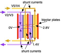
For the "large-format" cell, we'd like to target as large of a geometric area as possible, and ideally have the flow frame be useable both for single-cell and stack testing. This means it needs to possess adequate internal fluid manifolds and flow diffuser/spreading geometry. We must also consider shunt currents once we progress to stack testing, so we'd like to design the cell with that issue in mind upfront.
We plan to start with a flow-through design, as it is much, much simpler to design and manufacture than flow field-based approaches.
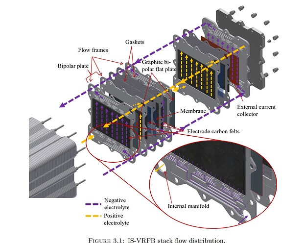
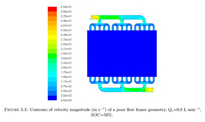
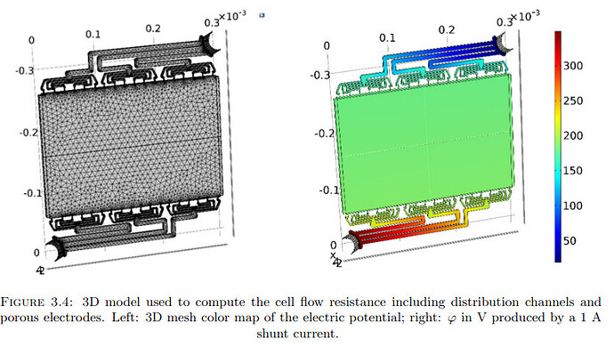
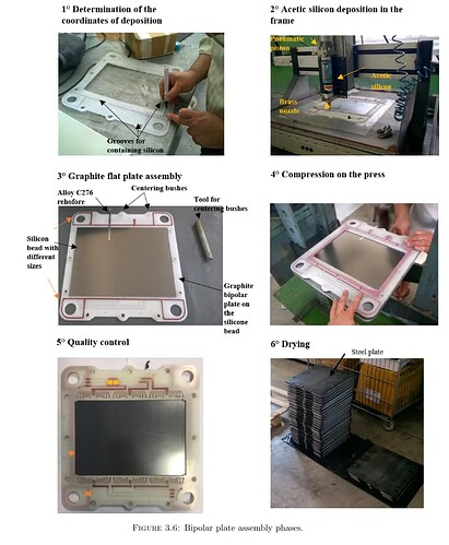
This thesis has some helpful figures - I haven't read it yet myself, but it looks quite useful. The author is now a professor at University of Padua.
Basically we want to make our own version of this. Ideally we could prototype it with polypropylene FDM printing... but in any real application it would be injection molded.
A good image showing the path of a shunt current, which leads to a drop in energy efficiency as well as uneven current distribution (and possibly plating, for hybrid RFBs):
Did another leak test today with water, correctly with 2x ~12 mm plywood endplates each side. Saw no leaks through the edges which was great news, but the barbed connections on the cell showed signs. Also, the MP-6R pumps struggle with the current flow frame design, which has 0.8 mm wall thickness and a 1 mm internal channel (electrode area therefore 2x0.8 + 1 = 2.6 mm thick). I remade (and pushed to the repo) the flow frame with a 3 mm internal thickness, in order to alleviate this pressure drop.
Here is the test setup, I ran out of tubing (ordered 2m but they sent 1 m ), so the connections aren't ideal but this time no kinks in the flow path. Note, I put these drain valves in, of course they are pointing the wrong way for now, will need to elevate the setup so they can point down in the future.
[image: 1769764493660-9fafda86-7f70-439f-9ecb-eeb9a7316215-img_20260129_153901-resized.jpg]
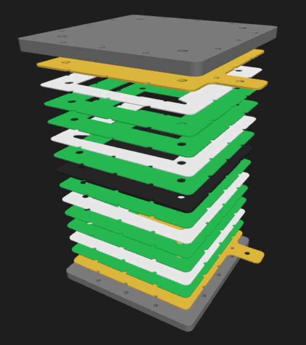
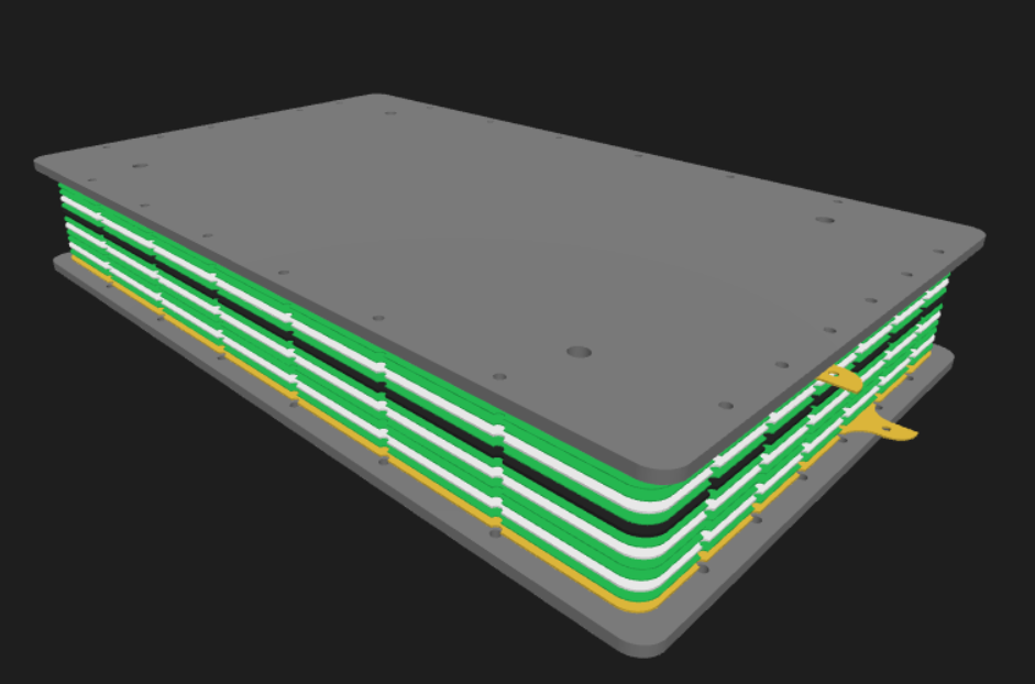
Because all the connections are on one side (in anticipation of stacking these cells), I also made "front" and "rear" versions of endplates, inner/outer current collectors, and gaskets in the FreeCAD files. This will make low-volume prototyping a bit more expensive but more robust against leaks, which no one wants!
[image: 1769763690358-037a7741-97dc-4012-8e95-cf8ab8760653-image.png]
This is the dimension that went from 1 mm to 3 mm to facilitate using MP-6R pumps.
[image: 1769763764115-d4ac6efb-4694-4d13-a941-8ffb85995001-image.png]
We have the MP-6R now. It is the 6W high-flow version. the MP-10 is also 6W but lower flow / 50 % higher max pressure, then the MP-15R can do almost 3x higher pressure than the MP-6R but at 10 W.
@danielfp248 can hopefully print the 3mm flow frames and I can get them at FOSDEM, then try them out. If it turns out we need the bigger pumps, I'll order them from AliExpress:
[image: 1769763852108-f14b9379-cbc5-4542-940c-b33c0bacdb14-image.png]
as part of the CIRCLE project at the Bochum University of Applied Sciences, our student group is preparing to conduct a life cycle assessment (LCA) for the Flow Battery Research Collective’s open-source redox-flow battery. If possible, we would like to take a look on the upscaled cell/stack/battery.
During our Zoom meeting on 19. November 2025, you shared several ideas for meaningful LCA topics. Based on your input, we developed two possible options that could support the ongoing development of the battery. To proceed, we would like to know which option you prefer or where you can provide the most useful data.
Option 1: Electrolyte–Membrane interactions
This topic focuses on how the electrolyte composition and membrane material affect each other, especially regarding efficiency and degradation. Goal:
To assess the environmental impact and technical relevance of electrolyte–membrane interactions, and to perform a screening comparison of membrane and electrolyte choices from production to end-of-life. Information we would need (please provide as much information as possible):
• How the selected electrolyte interacts with different membrane materials and which parameters are considered for choosing the electrolyte-membrane pairing
• Measured efficiencies of the current electrolyte-membrane selection
• Background on membrane selection in the development kit (e.g. which specific materials were chosen and why)
• How is the material wear currently counteracted (replacement only)?
• How is waste (wastewater, solid waste, co-products from chemical manufacture) disposed of?
Option 2: Electrolyte Leakage
Leakage is an important practical and environmental concern, and understanding its causes could support improvements in design, sealing, and material choice. Goal:
To analyse the environmental implications of electrolyte leakage, identify contributing factors, and explore what design or material changes might minimise it. Information we would need (please provide as much information as possible):
• How frequently leakage occurs (per cycle/per kit/in what percentage of the kits)
• How leakage is currently detected (refill volume, reduced power output, emissions, etc.)
• Whether it is monitored proactively or noticed after cycle completion
• Estimated amount of electrolyte lost per cycle
-> If no data is available, could it be collected by measuring leakage over multiple cycles?
• Whether leakage becomes more common with aging or due corrosion
• Current methods or design choices used to minimise leakage (e.g. sealing, welding, bonding)
We also have some general questions. More questions will probably arise in the future. General questions:
• How much energy supply does a RFB require (for one cycle/in total)?
• Which electricity mix is currently used to operate the battery (is there a proportion of green electricity)?
• Where are the materials purchased? From which countries are they delivered and how (train, car, ship)?
• In which country are the batteries assembled and tested?
We would be happy to work on either topic, and we aim to select the one that is most helpful for the FBRC team and for which the necessary data can be provided.
We look forward to hearing your thoughts and continuing our collaboration!
Kind regards,
Rieke Huesmann, Anita Thaqi, Stella Vucemilovic
Hi all, and apologies for the delay! This year has started off with quite a lot of administrative burden for me and I haven't had as much time for research as I anticipated.
@Santiago-Eduardo said in Life Cycle Assessment (LCA) for the FBRC redox-flow battery:
Elektrolyte:
The group noticed that two slightly different electrolyte compositions are mentioned.
Sorry for the confusion, the correct mass composition can be found in the documentation here: https://fbrc.codeberg.page/rfb-dev-kit/electrolyte.html, the masses listed will prepare approximately 10 mL of electrolyte.
@Santiago-Eduardo said in Life Cycle Assessment (LCA) for the FBRC redox-flow battery:
They assume an 880 ml volume for one single cell. Do you estimate this volume to maintain the obtained results until now? Is this the volume foreseen to achieve the 22 Wh/single large-format cell?
Yes this would be correct volume scaling for the large-format cell, although of course still a lot smaller than an eventual life-size system! It is basically t]e volume that we will end up using for our tests of the large-format cell (still to come).
@Santiago-Eduardo said in Life Cycle Assessment (LCA) for the FBRC redox-flow battery:
The group is assuming the EE value to estimate this. This value does not include energy demand from pumps and electronics, correct?
Correct, these losses are often summed up in RFB literature as "balance-of-plant" or BoP if you want to search for some values.
@Santiago-Eduardo said in Life Cycle Assessment (LCA) for the FBRC redox-flow battery:
Meaning: to store 1 Wh, 1.56 Wh needs to be taken from the grid (excluding electronics and pumps). Does this make sense, or are we oversimplifying here?
You've got it exactly!
@Santiago-Eduardo said in Life Cycle Assessment (LCA) for the FBRC redox-flow battery:
Used electricity
For the same purpose of modelling the use phase, it is important to define from which country and what type of energy/electricity is being used to charge the electrolyte. Since the users of the FBRC battery can be anywhere, but are currently mostly centered in Europe, the group has decided to choose the European electricity grid mix data to represent the current FBRC reality.
This makes sense to me.
@Santiago-Eduardo said in Life Cycle Assessment (LCA) for the FBRC redox-flow battery:
The separator, for instance, would be one of these peripheral impacts, since it would need to be replaced after some cycles (probably faster than the electrolyte). Since cycle durability of photo paper is still unknown, the group will model different scenarios from 10–100 cycles in steps of 30 cycles. Do you feel this is a reasonable range? Do you already now conditions such as density and flow rate the larger cell will work with? The group will assume 4 layers for the larger cell although in some parts are 3 layers stated.
While separators can be replaced, I am doubtful in an industrial system that they would, due to the labor costs. From my understanding, Li-ion lifetimes are often given as 2,000 cycles to 80% of initial capacity; for flow batteries, the data isn't as solid, but for VRFB the lifetime claims are more on the scale of 20,000 cycles or 20 years, whichever comes sooner (taken with a grain of salt...). We haven't done any testing that long-term, so don't have much for your to extrapolate, but RFB technoeconomic papers with operation and maintenance (O&M) costs incorporated would give you a good idea of membrane/pump replacement
frequency (if ever). I would increase the cycle range to much longer terms, with the upper end in the 1,000s at least.
We aren't yet locked-in on flow rates for the large cell as we are still settling on choice of pumps and flow field design.
@Santiago-Eduardo said in Life Cycle Assessment (LCA) for the FBRC redox-flow battery:
The current BOM and building instructions do not provide specific links to purchase the necessary chemicals. To model the electrolyte production, including the transportation of each chemical, the group has assumed the following production locations based on market data and worldwide production trends. If your own experience differs in this, please do not hesitate to comment.
These assumptions all make sense to me; Daramic separator (which we also use in addition to paper depending on the test) can/is produced in the EU though not exclusively.
I hope this clears things up for you all somewhat, and again, sorry for the delay!
I didn’t want to take over the “New member introduction thread” with my questions, so I’ve started a new one.
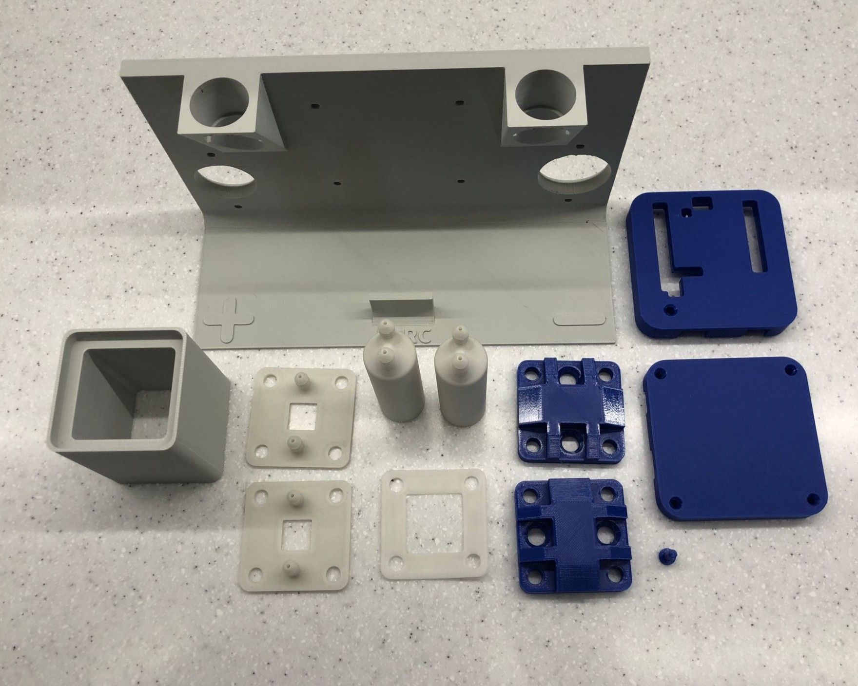
At this point, I already have the 3D printed components. I should receive the remaining parts later this month.
One thing I was missing in the documentation was information about the material for the "polymer endplate". In the photo, “PETG 100%” was written on the endplate with a marker, so I used that material and infill.
@danielfp248 I always performed more cycles before starting 40 mA / 100 mAh charging (10 half-cycles at 20 mA / 10 mAh + 4–10 half-cycles at 30 mA / 10 mAh). The cell was also wet with demineralized water (leakage test). Could this also be the cause? I was also always using the membrane frame. Wouldn't the electrolyte leak through the paper membrane?
@kirk Apart from solving the electrolyte leakage issue, does this "pulling-through configuration" improve the total capacity of the system in any other way? Also, I am wondering whether you are using the default flow frame from the documentation (2 mm thick, right?) or a different one with another thickness and the 0.1 mm silicone gaskets.
I have still not been able to test my cell because I wanted to make sure I had my mystat calibrated correctly. For this I wanted to implement a calibration wizard. Unfortunately I was not prepared to deal with the very large single file, single layer codebase of the mystat control software. I therefore had to start refactoring this code. My progress is visible here: https://codeberg.org/sepi/mystat/src/branch/feat-refactor-modular
The advantages of my refactor are amongst others the following:
less global state, easier to understand code
multiple smaller modules making it easier to find code
layered architecture, separating concerns more cleanly
"plugin" system for easier extension
easier testing of both hardware code and gui code due to decoupling into layers. A mock hardware class could be implemented to test the gui or other Tabd could be implemented as new classes
availability of decoupled hardware layer that can be used independently of the gui
easier implementation of new "Tab plugins" by subclassing and using the hardware and gui layer.
This is still work in progress and probably pretty buggy. I tried not to touch any of the implemented logic but there afe surely some problems left. Once I'm done with the refactor, I would like to write a wizard for calibration hoping to make it obsolete to consult the original paper for reference.
I'm open for comments and suggestions now and help with testing once my branch has stabilised a bit.
Hi sepi, your refactor-modular works on my PCs: my mainPC (Kubuntut 2404) and two Notebooks for measurements (Kubuntu 2404 and Win11), thanks.
I'm waiting for your calibration wizard. My hardware is waiting incl. Mystat, but till now I did not do tests.


