Skip to content
  • Systems engineering and modeling

    General Discussion
    9
    0 Votes
    9 Posts
    788 Views
    M
    @kirk @sepi I think Bert's models are free to download off his site, but if you wanted to read the paper, I'm happy to email them to you or you can reach out to him for a copy.
  • Sourcing parts

    General Discussion
    20
    5
    0 Votes
    20 Posts
    1k Views
    kirkK
    On it, thanks @sepi !
  • All-copper

    Electrolyte Development
    14
    2
    0 Votes
    14 Posts
    1k Views
    D
    @Vorg The reaction is not of elemental iodine with Zinc metal, it is of triiodide with Zinc metal. While this reaction is very exothermic, it is not explosive in this context because of a few reasons: While all the Zn is deposited at the same spot the oxidized iodine is distributed through the entire catholyte volume, so if the membrane ruptures it takes a while for the reaction to happen, it doesn't all happen at once. There is a lot of water here, which carries a lot of thermal load. While you can generate a lot of heat on membrane rupture, it isn't even enough to boil the solution at 100% SOC (from my experience). Per point 1, only a small fraction of iodine is able to react at any given point and for more to react flow must be present. Zn here is bulk Zn, it is not powedered or finely divided at all I have seen this happen experimentally at high SOC at 2M KI using photopaper. The membrane ruptured at high SOC and what I saw was the volume all shift mostly to one side and the potential drop very quick. Nothing exploded, melted or anything that dangerous. Untreated photopaper is obviously not intended to be a long term use membrane, it is intended as a viable membrane to carry out short term testing that is very easily accessible. To use it long term it is necessary to increase its lifetime with a PVA coating or something along these lines. The most dangerous scenario in my experience is solid iodine forming in the cathode, blocking flow and causing tubing to unhook, this then splashes charged electrolyte, which is a considerably greater hazard. The use of triethylene glycol seeks to mostly prevent this scenario, but it is still possible if very high currents are used or the cell is overcharged to high potentials (>1.6V). With the above said, the anolyte and catholyte hold a lot of energy and mixing them obviously instantaneously discharges all that energy. At 10mL of total volume this is not much, around 250mWh but when using larger volumes this is a considerable risk and larger scale devices must be created and tested with this potential scenario in mind. 
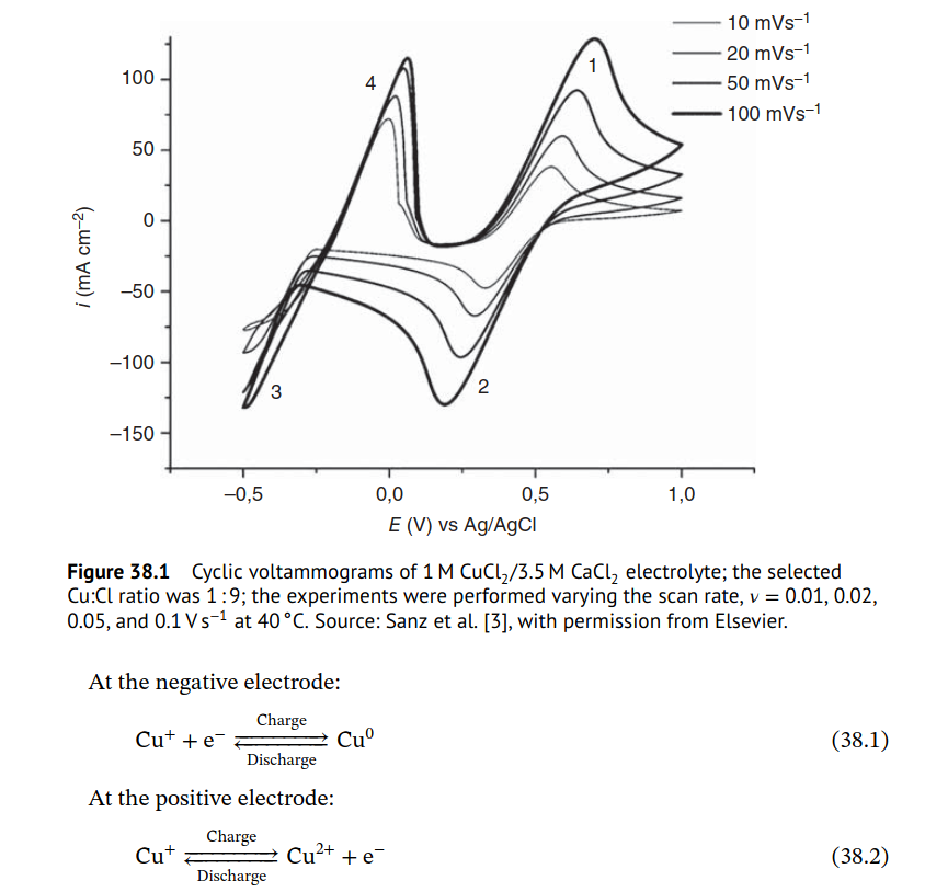
About the copper, oxygen in it would ruin the electrolyte because it would oxidize Cu+ to Cu+2 and this reaction would also increase the pH of the anolyte. This would eventually cause Cu hydroxide to fall out and kill the device. To recover the cell you would need to purge the electrolyte with Argon, cycle the solution over Cu metal to reduce the oxidized Cu2+ back to Cu+ and add hydrochloric acid to adjust the pH back to the proper level if necessary. To run a cell like this you need to make the system quite airtight and ensure the electrolyte is purged with Argon from the start. An idea to test for a period under oxygen-present conditions is to keep a piece of sacrificial copper in the anolyte reservoir to make sure that any Cu2+ that is formed is reduced back, so that way you would only succumb to the slow pH up creep. However this means that the CE you measure isn't really fair, because you are not accounting for a huge chunk of active material present there. It can be useful however to cycle and perhaps get some insights into other sections of the system under a regular atmosphere. However I don't honestly know if this is good enough, as the reaction of Cu+ with oxygen is quite fast. The copper chloride (I) initial electrolyte is usually prepared like this (under copper metal) to make sure there is no Cu2+ present when first loading the electrolyte into the device.
  • 0 Votes
    8 Posts
    686 Views
    J
    Ah, in the FAQ ... Yes, was thinking wrong from other and not so good sources.
  • Connecting potentiostat

    General Discussion potentiostat documentation help
    10
    1 Votes
    10 Posts
    912 Views
    D
    @sepi Unless you are very experienced soldering small components I would suggest not doing this. Some of the expensive components are tiny and easy to damage, either by overheating or by soldering multiple legs together and causing shorts. I tried soldering my own mystat 3 times (without success) before I got my first working one from pcbway. I am however, not good at all at soldering.
  • MyStat PCBWay Component cost

    General Discussion
    4
    1
    0 Votes
    4 Posts
    296 Views
    sepiS
    My latest quote is 315$ with assembly included by PCBWay. That's expensive but not prohibitive. Thanks for the input!
  • 2 Votes
    15 Posts
    1k Views
    V
    I'm no expert ether. We used quick setting plaster a lot in construction for repairs on a lot of things and now they have a "wood epoxy" which is an epoxy for wood repairs. You have a thing epoxy you brush on onto wood which provides a good bonding surface for dry rotted wood and then you mix an epoxy that works more like the quick setting plaster and creates a strong enough repair that you can nail it. These plasters and epoxies could be formed or poured to create a nice mold. For the quickset we could build up an area, then carve and shape it before it fully set. The surface is very smooth and with a spray sealer of some kind should be even better for molds. A quick look into casting, it looks like the most common is using silicon for making the mold. Yes it lets you do detail, but it is also soft and flexible. Not good for making thin plates without warpage.
  • Diagrams of load / unload efficiency?

    General Discussion
    1
    0 Votes
    1 Posts
    131 Views
    No one has replied
  • Assembling the FBRC flow cell (rough cut)

    General Discussion
    4
    0 Votes
    4 Posts
    356 Views
    kirkK
    Here is an updated version! https://spectra.video/w/nJ8XNYu1MXNPSDLKV3KVTh
  • 0 Votes
    1 Posts
    376 Views
    No one has replied
  • 0 Votes
    1 Posts
    239 Views
    No one has replied
  • Choice of plastic

    General Discussion
    5
    2 Votes
    5 Posts
    484 Views
    kirkK
    @gus @SamAuc ABS may work with an all-copper chemistry!
  • Zinc-Iron

    Electrolyte Development
    1
    1
    0 Votes
    1 Posts
    268 Views
    No one has replied
  • FAIR-Battery Project website review

    Blogs
    3
    0 Votes
    3 Posts
    435 Views
    kirkK
    Hi Otmar! I think it would be helpful to see a rough schedule of the workshop and time allocations per topic/activity - then it would be easier to give feedback for the site, based on specifics of the activity the site is meant to complement!
  • Made a video on FreeCAD for FBRC contributions

    General Discussion
    2
    0 Votes
    2 Posts
    177 Views
    K
    Cloning the https://codeberg.org/FBRC/RFB-dev-kit repository, opening the assembly in FreeCAD, fixing part of it, then pushing the changes with VSCodium. As part of the Flow Battery Research Collective project at https://fbrc.dev 0:00 Cloning repository 3:29 Opening assembly file 4:09 Fixing the cell assembly 20:20 Pushing changes to repository
  • Hi!

    General Discussion
    2
    2 Votes
    2 Posts
    182 Views
    kirkK
    Hi Otmar, welcome to FBRC and the project, looking forward to working with you!
  • 0 Votes
    25 Posts
    3k Views
    kirkK
    @kirk said in How should we control the centrifugal pumps? TRIAC/thyristor etc? Need help from controls/electrical people: It seems to work! At least enough for testing purposes. Here is a video: https://spectra.video/w/8xipM8aXnBkDXnu4kkRpqT Here is the code for this test: https://codeberg.org/FBRC/RFB-test-cell/src/commit/d10834bc7dd67736e708c9a33832a5602ab3ca28/firmware/FlowrateRampTest.ino
  • 1 Votes
    2 Posts
    538 Views
    kirkK
    Nice work, Daniel. I am thinking of plumbing solutions to the imbalance issue: From A review of all-vanadium redox flow battery durability: After studying the capacity fade for mixed acid electrolyte, UET [154] found that, during long‐term operation, the ratio of catholyte and anolyte concentration remained constant: 1.3:1. Based on this finding, they designed an overflow system with different volume (volume ratio: 1.3:1) anolyte and catholyte tanks, in which the volume ratio and total vanadium were kept constant. With the new design, the VRFB achieved long term capacity and efficiency stability. However, this design is only valid for the mixed acid electrolyte system. Recently, Wang et al [152] developed an electrolyte reflow method to solve the electrolyte imbalance issue for the sulfuric acidvanadium electrolyte system. Figure 10 shows the schematic of their method; without reflow, eventually all of the anolyte will move to the catholyte tank, while with reflow, the anolyte tank will always contain some electrolyte. Similar to the UET method, the volume ratio of catholyte to anolyte is a key parameter affecting the capacity stability and is highly dependent on the operating current density. Cycle life and total capacity were all improved with the reflow method. There is also Capacity balancing for vanadium redox flow batteries through electrolyte overflow but it was retracted - they think they accidentally had a pinhole in their membrane for the test. But they did build a real overflow system: [image: 1739741378711-aceadcdb-fb4d-4387-b6c6-9b95a79cc192-image.png]
  • Micro-update

    General Discussion
    4
    4
    2 Votes
    4 Posts
    495 Views
    kirkK
    That's great! Do you have a link to one or know where we could procure one to test?
  • CI/CD

    General Discussion cicd
    5
    1 Votes
    5 Posts
    412 Views
    kirkK
    Stephen Hawes of Opulo has compiled some of their tools here: https://midscale.io/docs The AutoBOM one seems to be based on those workflows above and looks pretty interesting

1

Online

80

Users

59

Topics

626

Posts