In the hope that it will be useful to the future work of folks here, I've written up as much as possible about my experience patching up a failing ZCell and nursing it along. I've also included some further general notes about Redflow's hardware and software:
World
Topics from outside of this forum. Views and opinions represented here may not reflect those of this forum and its members.
-
Everything about energy production and storage.
Related communities:
-
-
A world of content at your fingertips…
Think of this as your global discovery feed. It brings together interesting discussions from across the web and other communities, all in one place.
While you can browse what's trending now, the best way to use this feed is to make it your own. By creating an account, you can follow specific creators and topics to filter out the noise and see only what matters to you.
Ready to dive in? Create an account to start following others, get notified when people reply to you, and save your favorite finds.
Register Login-
 Hello! I'll try to document my building experience here while I impatiently wait for parts to arrive. This is mostly to document and motivate myself to continue. Don't expect super interesting stuff in here.
After having ordered most of the material from aliexpress and amazon.de, I finally got around printing the endplates yesterday. I opted for PLA on my old ender 3. As described in the docs I went for the 60% infill and managed to produce some pretty decent parts. The layer height of 0.25 looks good too. Each plate took around 1h30 on this antique machine. There might have been a tiny bit of warping on one edge but I hope it won't be enough to cause issues.
Anyways, I still need to print the arduino case and the stand (which I might modify in order to use less material). On the ordering front, I still need to order most reagents from synthetica and some PP-filament.
@sepi Without the four-wire control the pump speeds are definitely harder to manage, sorry to hear that, though the PWM regulator may help. Can you visually see how different the rotation speeds are? That should be rough proxy for volumetric flowrate. I am not surprised they won't spin below 11 V. @sepi said in My build (very slowly progressing): Is this 20-40ml/min measured with the cell in line or just the pump. Ideally best to measure with the cell inline, to be closer to the actual conditions. However, as the tubing wears, this can drift, just FYI. Not a huge deal but something to be aware of. @sepi said in My build (very slowly progressing): Is the figure obtained with water or electrolyte? Water for now, just as a proxy, minimize exposure to electrolyte. This is kind of a 1, maybe 2 significant digit measurement, no more (the volumetric flowrate). @sepi said in My build (very slowly progressing): What would you recommend doing against the excess flow? @sepi said in My build (very slowly progressing): the left passing up to 40% more water at the same voltage. At the same voltage, is the left pump spinning at (nearly) the same rate as the right? if they are spinning at the same rotational speed and the left is passing 40% more water, it sounds like there is some flow restriction in the right pump's flow loop. If they have identical flow loops (in terms of pressure drop), and are set at the same voltage, I would guess that they should rotate at similar speeds, but this may not be the case for the brushed motors (e.g. variance in motor properties). What is important for testing, is that both pumps are above a minimum flowrate to ensure good mass transfer, and that the pressure imbalance between the two sides isn't too great as to cause transfer of electrolyte from one side to another through the separator. If the flowrates aren't perfectly matched but those two previous conditions are met, it's not a big issue, although it's just better for repeatability for them to be the same. -
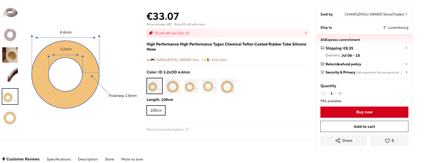
Hello fellow flow battery enthusiasts! I bought 15m of Tygon Chemical tubing with PTFE lining suitable for the Zn/I chemistry as used in the devkit. I only need around 2m and someone else wanted to take 5m, that's 8m left to be distributed amongst people who need some. I ship in the whole EU and the price is 23€/m (thats what I paid incl. shipping). Just send me a PM if you're interested.
-
Hey Everyone. I designed and printed some PLA sleeves to go over M6 screws so that you don't need to use tape on the screws anymore with the kit. The tape is often hard to properly wrap around and imo has to be changed quite often, so this should improve the design. I printed these on a Prusa Core One using a 0.4mm diameter nozzle. The screws don't come into contact with active material, so you can use PLA for this (doesn't have to be PP, although this should also work).
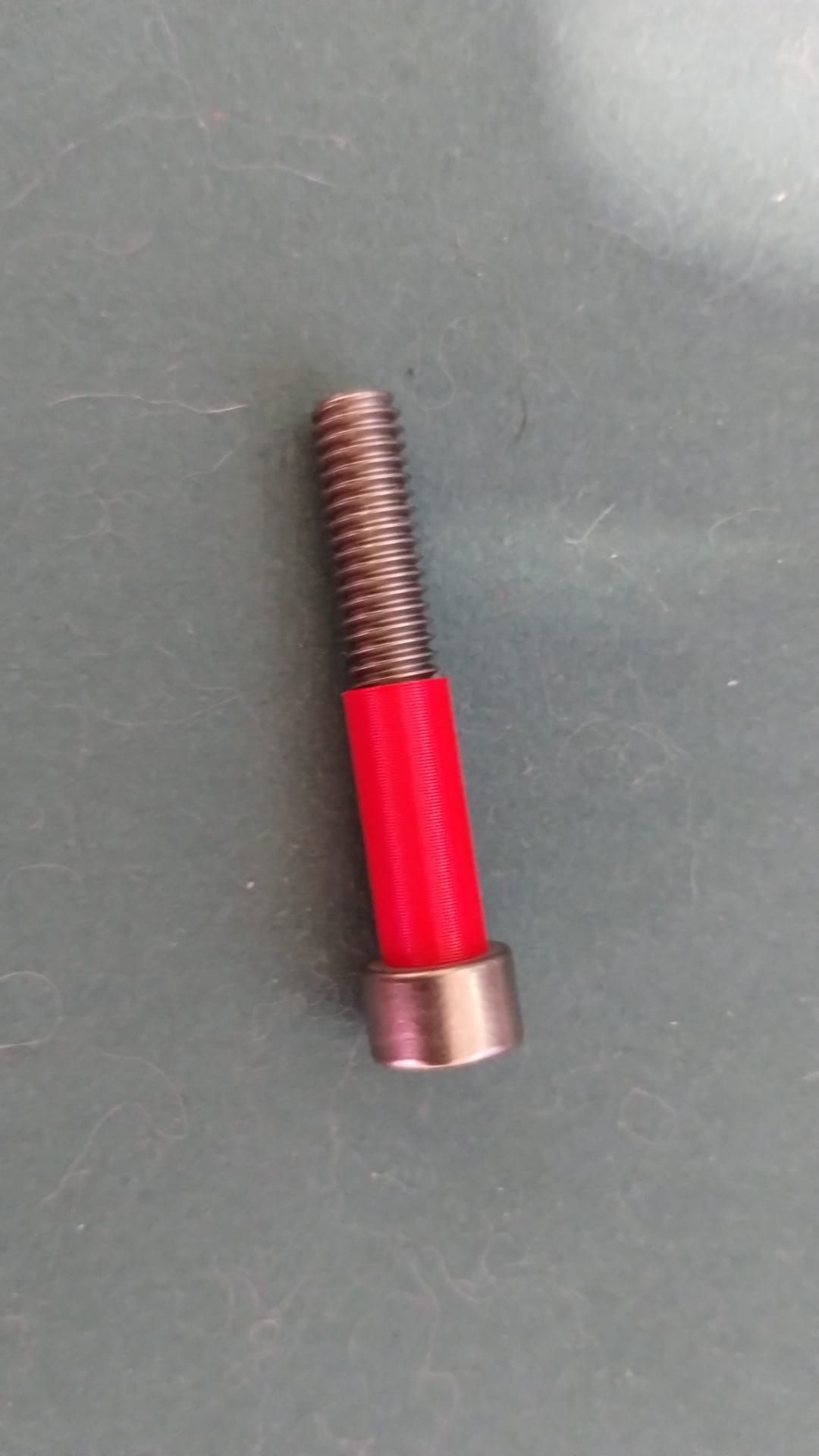
You can get the STL here:
You can print these in "vase mode" so that you have no stitching marks. Let me know what your experience is with other printers!
-
-
@danielfp248 I ran into some of your old work on Fe-Mn batteries. I've been interested in Fe-Mn batteries for some time and was wondering if you could share some of your experience.
In particular, if we look at the pourbaix diagram of Fe and Mn overlapped, there's a region in the pH 4-6 range where Mn2+ oxidizes to MnO2 and Fe2+ reduces to Fe on charge.
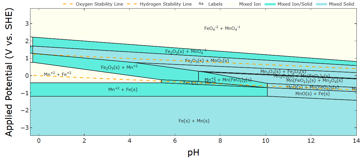
Let's say we can ignore the fact that there are solid phases - then ion crossover poses a long term concern. Have you guys found any inexpensive or DIY ion selective membrane options (either specific to a particular ion or broad spectrum diy anion/cation exchange membranes?) In my experience screening for inexpensive battery chemistries, crossover of solution phase species is a problem I haven't really seen an easy DIY solution for. Not that I've looked super hard!
-
All-Fe flow batteries are very promising due to iron’s high abundance, low toxicity and low cost. In these batteries, FeCl2 is used as the main active salt in solution. When charging Fe2+ gets reduced to Fe metal on the anode while Fe2+ gets oxidized to Fe3+ on the cathode. However, these batteries suffer from a fundamental problem that has made their large scale adoption very difficult up until now.

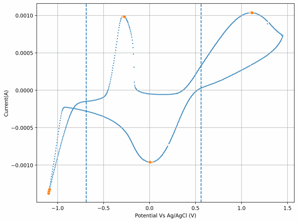
Cyclic voltammetry of 1M FeCl2 and 4.5M CaCl2 using an Ag/AgCl reference electrode and a glassy carbon working electrode. The main limiting problem of these batteries is H2 evolution at the anode. Since Fe plating happens at a lower potential than H2 evolution, there is always some hydrogen generation when the battery is charged. This H2 evolution causes an increase in the pH of the battery which then causes iron hydroxides and oxides to precipitate out of solution. This causes passivation of Fe metal surfaces, loss of capacity and potentially clogging of the battery.
A few years ago, Tao Gao’s group in Utah discovered that CaCl2 and MgCl2 water-in-salt-electrolytes (WiSE) (read the paper here) could substantially improve Fe plating behavior. While they didn’t test this in flow batteries, they showed that very high Coulomb efficiencies with very low hydrogen evolution rates were possible when using these salts. This is because these salts bond with water and therefore make it substantially harder for water to get reduced at the anode. We are talking about very highly concentrated solutions though, around 4.5M CaCl2, which is around 660g/L of CaCl2.2H2O.

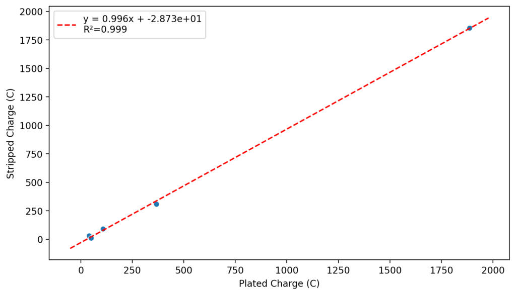
Plate/strip experiment using the 1M FeCl2, 4.5M CaCl2 electrolyte. We recently obtained some of these reagents to test these chemistries in our flow battery kit. I first ran CV experiments of the 4.5M CaCl2 electrolyte with 1M FeCl2 and obtained the curves showed above. This reveals standard potentials of -0.71V and 0.55V for the two half reactions, which means our battery should have a max potential of around 1.26V. I then ran plate/strip experiments (using different plating times), which generated the second curve above. Using the slope of this plot we can extract the plating efficiency, which is >99% in this case. This means that very little hydrogen evolution is happening within this electrolyte, a result I had never seen with FeCl2 solutions and which is in agreement with the Tao Gao group paper.
After doing this I then ran a flow battery using this electrolyte and noticed some problems with capacity loss because of undissolved metallic Fe on the anode using a Daramic separator. It seems that the above electrolyte has some issues with the reversibility of the plating reaction. While little hydrogen is generated on plating, there still seem to be some important losses of capacity due to passivation of the Fe. To fix this problem I then added 1M NH4Cl into the electrolyte, which helped me fix this issue when dealing with Zn-I flow batteries.

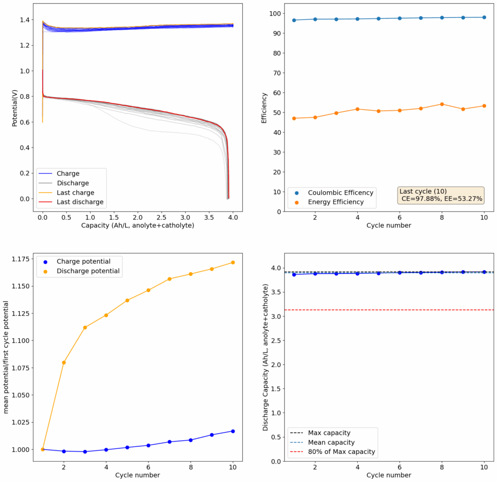
Cycling of an all-Fe battery using 1M FeCl2, 4.5M CaCl2 and 1M NH4Cl. Cycling was done at 20mA/cm2 Charging was done to 4Ah/L and discharge was done to 0V. I cycled the battery at 4Ah/L, which generated the results above. You can see that we get extremely good CE values (97.88%) which are even better than those we were obtaining with the Zn-I system, even though we’re using a microporous separator. The energy efficiency is lower than for Zn-I but still reaches a value of 53.27%. Given a concentration of 1M FeCl2 , 4Ah/L represents a state-of-charge (SOC) of ~30%. The cycling is stable, although some increase of the charging voltage is indeed happening through time (although this is also matched by an increase in the discharge voltage). The mean discharge potential is quite low though, at 0.7V, which means we have considerable ohmic losses at this current density.
I am now testing the electrolyte at higher SOC values and will continue testing MgCl2 and other modifications, such as additions of ascorbic acid and thiosulfate to remove oxygen from the initial solutions and improve the initial state of the battery (as some capacity is lost due to the presence of oxidized Fe in the initial solution). Make sure to follow our progress on this forum thread.

This flow battery kit work is being funded by the Financed by Nlnet’s NGI0 Entrust Fund. We are also collaborating with the FAIR Battery project.
-
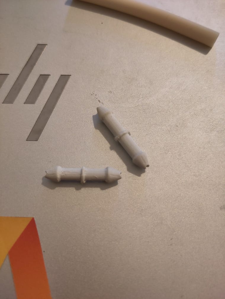
Hello everyone! I've had the idea floating in my head for quite a while to make my own barbed connectors/fittings for connecting tubing as used in the dev kit. I finally got around printing a series of prototypes in PLA. The results are promising, even if the value of printed ones is questionable. Designed them so that you print them lying flat in order to optimise lengthwise strength. To get them watertight, you just need to sand the barbs a tiny bit.
I have two main reasons to print these parts myself, first of all, I forgot to order them and secondly, the more parts of the dev kot can be printed, the less people will have difficulties sourcing them.
I'll publish a Freecad file once I have it tested and printed in PP.
My pumps didn't have them, only the ones built into the pump. I saw that on some of your pictures, you have additional fittings between the different elements, I guess to make it easier to connect and disconnect the cell. In the end, it might make more sense to just shrink the barbs on the flowframe and/or tank a bit so the tubing comes off mor easily. -
New Certified Open Source Hardware!
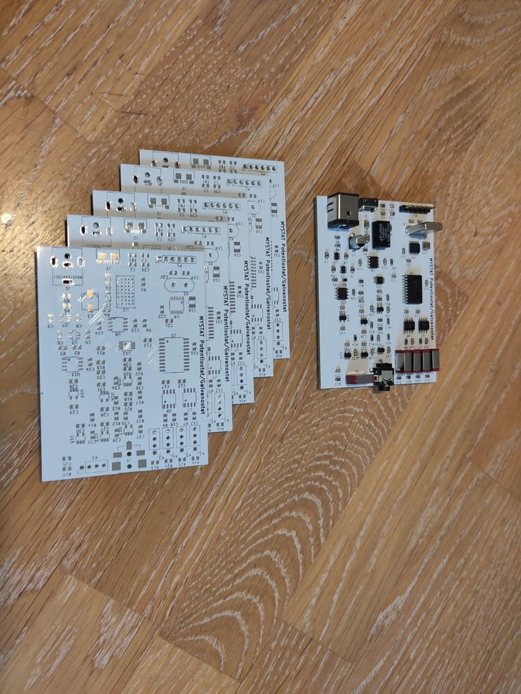
Redox Flow Battery Development Kit has the UID FR000028.
Redox Flow Battery Development Kit is:
This kit is for testing flow battery components and electrolytes at a benchtop scale (2 cm²) with an affordable, reproducible setup.Find it in the directory!
https://certification.oshwa.org/fr000028.html
-
@kirk So my thesis is specifically on slurry/suspension electrodes (instead of using a graphite felt/porous electrode, you suspend conductive carbons with the electrolyte - which also allow you to run solid-phase chemistries in flow) in a way that's sort of chemistry-agnostic. Basically applying chemical reactor design principles to designing slurry electrodes. But here are some salient idiosyncrasies of all-iron cells:
- iron plating in porous electrodes is annoying (acidic = HER, basic = whole host of nasty iron oxides, many of which are quite stable. Plating on carbon substrates is also a pain - most studies I've seen plate onto copper. Also volume expansion is a big pain in static cells. In flow batteries, any time you have plating you end up re-tying power density and energy density through that half cell. Iron plating kinetics are also quite slow, especially in relation to zinc plating.
- Bunch of folks (Savinell and Wainright groups) at case western used slurry electrodes and plated iron onto the slurry particles (ostensibly). They attempted to scale but really struggled with having a performant enough slurry electrode that wasn't too viscous. But plating on suspended particles re-de-couples power and energy density.
- Have you guys looked into water-in-salt electrolytes? They involve dissolving a ton of a supporting electrolyte to the point where they lower the activity of water and suppress HER. I've seen some work using acetate salts and this one using magnesium chloride to support even iron plating - and I've replicated it successfully. The study plates on copper like I mentioned earlier, but I also got it to plate on grafoil.
Solving that performance/viscosity tradeoff in slurry electrodes is part of my thesis! And so is improving the power density of otherwise crappy flow battery chemistries. I'm still working on getting some of it out, but I'd love to share soon or help in any other way.
Material choice from the perspective of mineral centralization and cost is another problem I think regularly about - I did a little study collecting the centralization/governance of various metals and ranked aqueous battery chemistries by cost and "criticality". If that's of interest let me know too!
-
I have started the first tests with the RFB. I have encountered the problem that the electrolyte migrates from one reservoir to the other. I assume that a better separator material would help. I am currently using three pieces of photo paper. Could more layers of photo paper reduce the effect?
The pumps I use are probably a little too big, which certainly doesn't help.
I assume that with larger cells, the problem will intensify and that a better separator material than photo paper will be necessary.It seems to me that there is no way to obtain small quantities of a proper separator. At least, I couldn't find any online.
Now to my actual questions:
What other materials could be used as separators?
Which one would be the most suitable to buy at the moment?
Has anyone of you been able to obtain small quantities of a separator material?
-
I know this is something for way down the road, but it seems to me there will be some kind of tank size limit. Because the bigger the tank, the more diluted the remaining charge would be when it gets low to the point that it would be of no use.
So any thoughts on what the upper useful limit would be on tank size before diminished returns kicks in?
-
I have so many questions that are related to RGBs but don't really fit into existing threads. I'll poste here and hope that we can collect those random questions in one thread such that we don't pollute the other threads too much.
-
I read about the history of batterie and it seems that for a long time, terracotta or other ceramics were used as membranes/separators. Have you investigated their use? Once I have a functioning system I will surely try it out. The advantages would be that they are tough (at least physically) and potentially easy to produce almost anywhere in the world.
-
I noticed that some designs of for FBs don't have flow frame like in the dev kit but rather a thin meandering channel. What's the reason for these two designs an why did you select the flow frame
-
What would happen if you just removed the membrane in the Zn/I cell, would the iodine anions just progressively oxidize the metallic zinc and produce heat?
-
Do I understand correctly that the Nernst equation can be used to predict at what temperature and relative concentration between oxidized and reduced ion of two species a redox reaction takes place? Do I also understand that this does not predict or influence kinetics?
Many thanks for your precious insights!
@danielfp248 sorry, my question was not well formulated. I meant a potential between the electrolytes inside the cell independently the possibility of measuring them using an electrode. Or to formulate it differently, if you cut through the cell (lile you cut a sandwich) and plotted the electrical potential between the electrodes, how would it look like? -
-
Hi Guys,
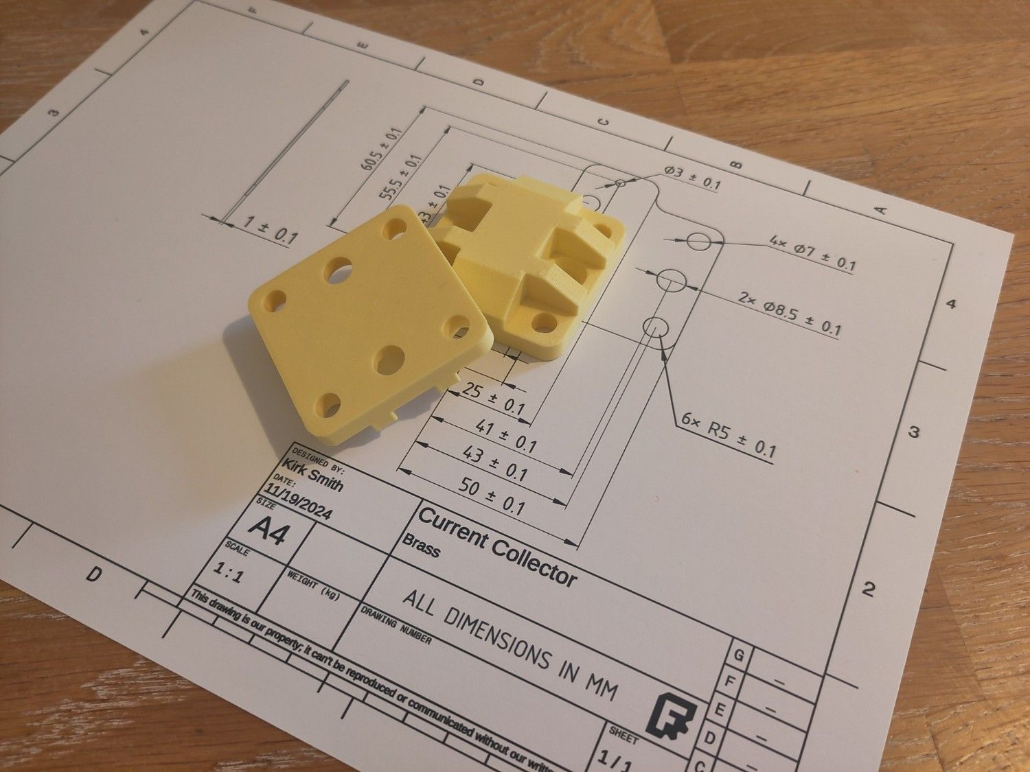
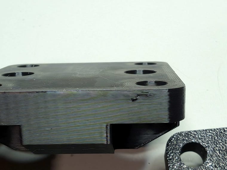
as promised I also want to document my journey on building the kit. Yesterday I started with the very simple endplates:
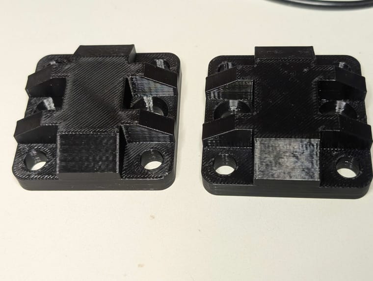 The right one was the first, printed with 15% infill, the left one with 60%, but still just 2 wall loops. Of course, you can feel the difference in the weight.
One problem I noticed was, that I had a PEI textured print plate only. Therefore the surfarce looks fine, but it might not be the best to seal the chamber.
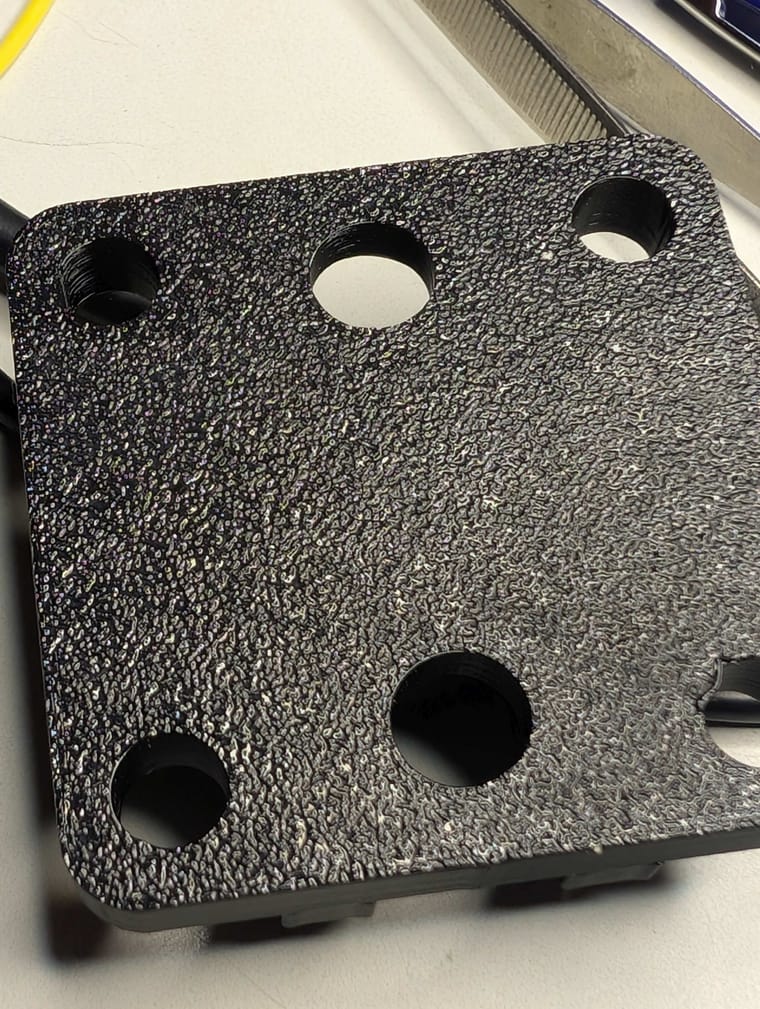
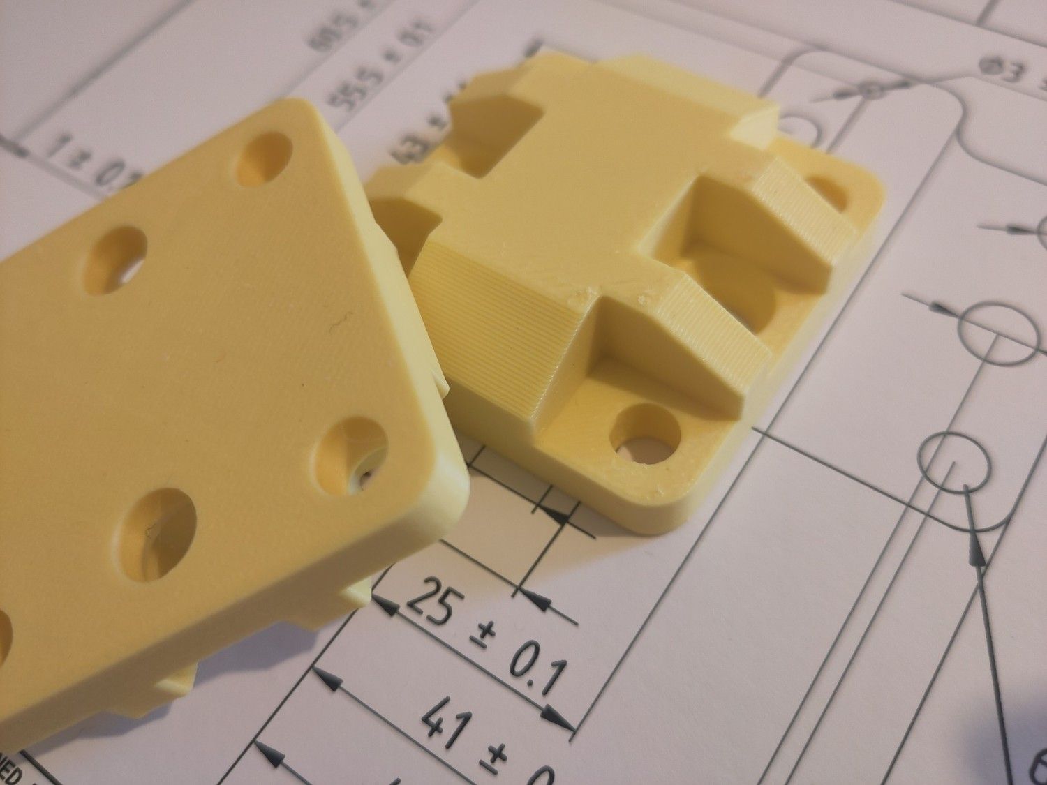
To solve this I ordered a flat "high temp" plate from Amazon, which arrived today. Of course, next print cycle was in the queue. This time with 5 wall loops:
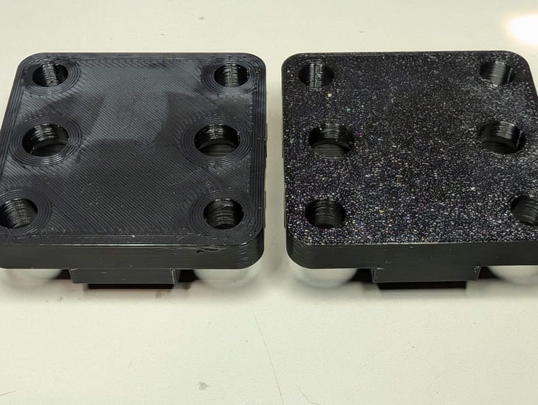
On the right the initial version, on the left the new one. You can see the difference immediately. Well, the picture still gives the impression that it is not flat, but it is:
This is how the old one was looking:
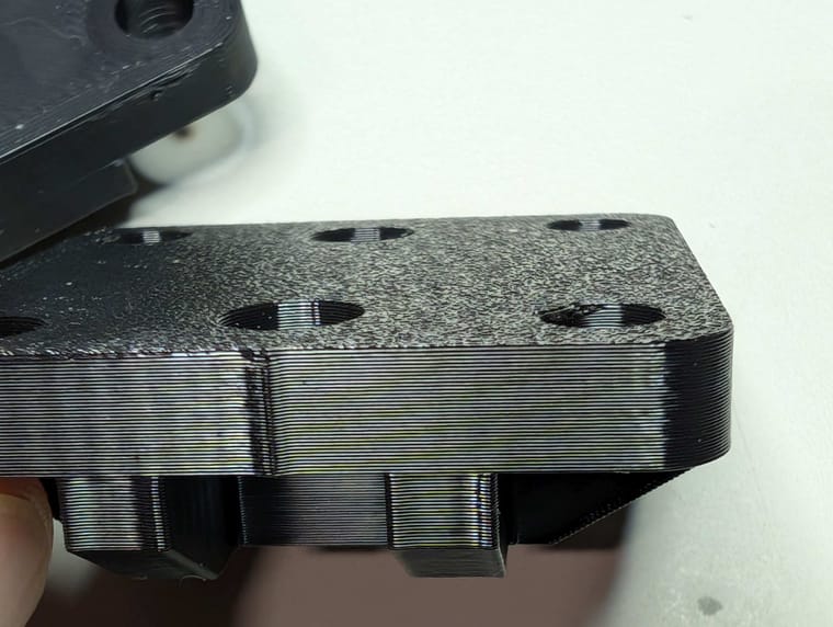
BTW, I printed all of them in Geeetech PLTG on a Bmboo Lab P1S with AMS. The printing time for version with 15% infill was arround 25min, 48min for the version with 60%. Printed with 0.2mm layer height.
Looking forward to print my first parts in PP in the next days...
-

Yeah… That went well.
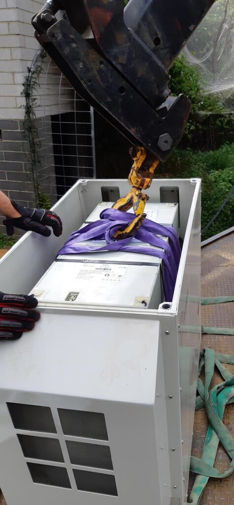
On December 14, 2024 – three weeks after I published the last exciting installment in this series of posts – our new Redflow ZCell battery, which replaced the original one which had developed a leak in the electrode stack, itself failed due to a leak in the electrode stack. With Redflow in liquidation there was obviously no way I was getting a warranty replacement this time around. Happily, Aidan Moore from QuantumNRG put me in touch with Jason Litchfield from GrazAg, who had obtained a number of Redflow’s post-liquidation stock of batteries. With the Christmas holidays coming up, the timing wasn’t great, but we were ultimately able to get the failed unit replaced with a new ZBM3.
At this point the obvious question from anyone who’s been following the Redflow saga is probably going to be: why persevere, especially in light of this article from the ABC which speaks of ongoing reliability issues and disturbingly high failure rates for these batteries. That’s a good question, and like many good questions it has a long and complicated answer.
[…]
-
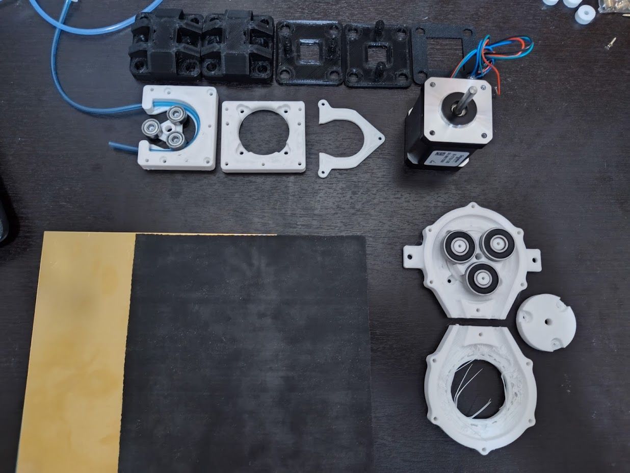
Inspired by Gus to share my journey. Some quite useful info in that thread. I expect my journey to be a bit more "scrappy", given I'm trying to make this work with some items I have lying around. I also might deviate on the first chemistry I test: we'll see.
For now here's a picture of some of the components I've printed, including two peristaltic pump heads that interface with NEMA-17 stepper motors and that use bearings as the rollers. Links to them here:
- https://www.myminifactory.com/object/3d-print-peristaltic-pump-63137
- https://makerworld.com/en/models/497147-peristaltic-pump-\_-nema-17-\_-608-bearings#profileId-622582
Small steps, hoping my next post is me showing whether I can get the pumps to work. I'd be curious if anyone has had success with such 3D-printed pumps. I'll try to provide some more feedback in the coming posts too.
@muntasirms Absolutely! A bunch of other great documentation on here, wanted to try to my part. I have a colleague who uses HIPS exclusively in strong alkaline systems. Significantly easier to print than PP from my limited experience. It's not pure polystyrene (which is great for alkaline), but the additive(s) don't seem to affect their tolerance too much. I'll keep you posted on compatibility as I test these systems! Not sure how long the parts will last yet. -
Hi all,
It's been very exciting to see the FBRC community grow these past months! We have come a long way from just two people tinkering in their respective apartments. If we are going to develop a practical battery technology in this way, having a strong open-source community will be crucial.
So far, all the interactions here have been positive to my knowledge. We've only had one blatant spam post so far. A few people I spoke with recommended adopting a code of conduct, such as the well-used Contributor Covenant. I have uploaded it to the FBRC website here and added the contact info for the current mod team (right now, me and @danielfp248).
I'm not adding this in response to any recent incident, rather, I think it's good to have it established and in-place as the community continues to grow.
If you have any comments or feedback on this, please feel free to discuss here! It's not a static document; we can change it as we see fit.
TL;DR: Don't be a jerk, let the mods know if someone is causing trouble, and let's make open-source batteries happen!
-
Hey all! If everything goes well, we'll soon have a bit bigger cell and maybe cell stack to play with. This will be another step towards building an actually useful energy storage. This also means that overall systems efficiency starts becoming an important issue. In order to know what to focus on in the development but also to understand questions of dimensioning and parts selection, it would make sense to be able to model the whole RFB system including Pumps, Inverters, plumbing and cell and its chemistry.
Did anyone look into this already? I was exploring a bit what tools we could use and figured that Libreoffice Calc would be the very simplest tool, followed by python with SymPy and finally by OpenModelica. What do you think? Is this the right time to think about these things or am I overthinking it?
-
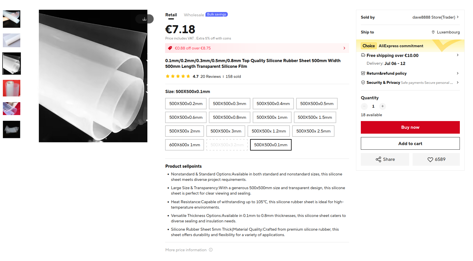
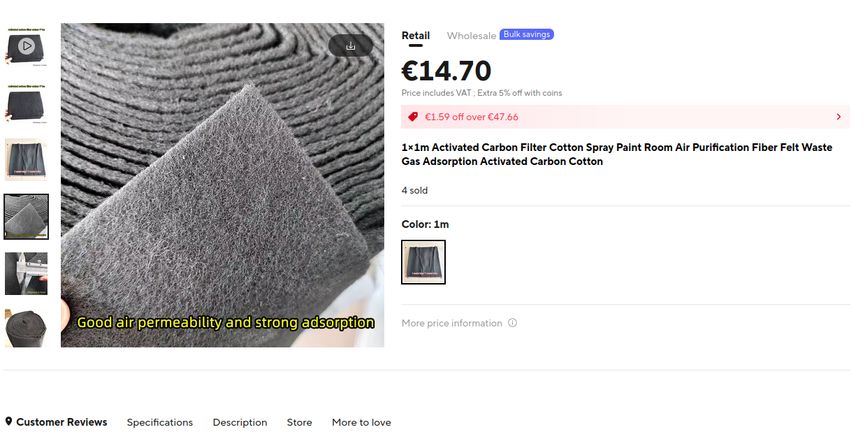
Hello all, I'm trying to gather parts but I'm not sure about some of the suppliers/products I have an eye on. Could you maybe give me some feedback about the following products? (I also added more specific questions to the screenshots).
Also, do you have any good sources for the chemical reagents that are accessible to amateurs?
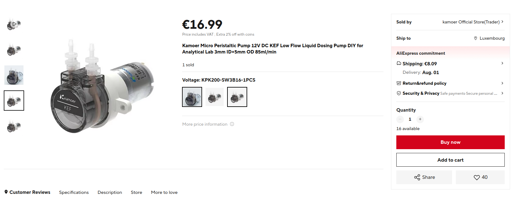
Did I understand correctly that there is a 12V and a 24V version with vastly different prices? The 12V one is 17€ while the 12/24V one 68€?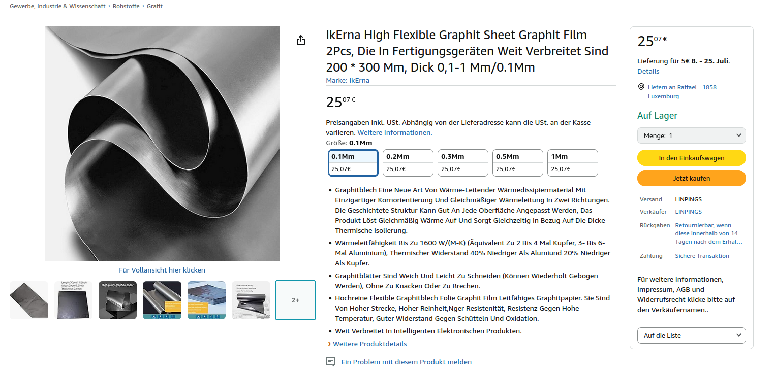
Many thanks for your help!